Cummins N14 Injector Troubleshooting and Repair "With this particular injector the way it works is that the solenoid is in an always open position allowing fuel from the rail into the injector and only closes during the downward stroke of the metering plunger so as not to allow the fuel to go back to the rail, rather trapping it in the injector and metering it to the cylinder. Technically, with this particular injector it would be more that the injector fuel supply is “closed” electronically at the injector. danielresume 6 months ago The solenoid is the only aspect of this injector that is electronic and governed by the ECM. It has been my experience that when these solenoids get weak or fail completely the engine might still run at idle without a misfire but under power will miss and have no power. The injector also has a ceramic check ball and metering plunger which will cause the same condition under power if worn as they will allow fuel to escape under pressure rather than injecting to the cylinder." I hope this Mechanic tip has been helpful.
Showing posts with label cummins diesel motors. Show all posts
Showing posts with label cummins diesel motors. Show all posts
Wednesday, September 28, 2011
Cummins N14 Injector Troubleshooting
I found this interesting video from a Mechanic named Daniel who posted an in-depth video on troubleshooting and repairing an injector miss problem on a Cummins N14 injector. This is an electronic diesel model that has solenoid controlled injectors pulsed by the engine ECM. It's an interesting video and very
detailed for the aspiring Cummins N14 Mechanic.


Saturday, January 29, 2011
Cummins Diesel Engine Fuel Injection Pump Installation
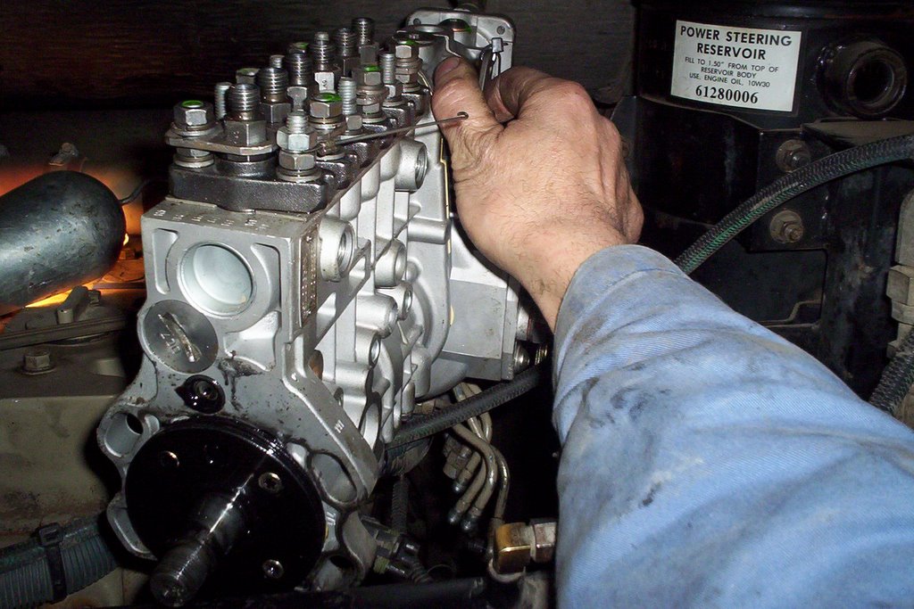 The Cummins Diesel [Engine Model 'C'] fuel injection pump has been repaired, but there are still a few steps to take.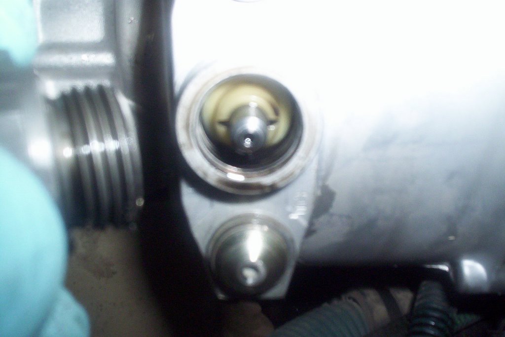
TIMING FUEL INJECTION PUMP:
The fuel injection pump MUST be timed by removing threaded hex cap located on the throttle shaft side of the housing. Remove timing pin from access hole and rotate the pump by hand until the timing tooth inside pump housing lines up with the middle of the access hole.
Engage slotted timing pin as the picture above shows. Install threaded cap hand tight until after injection pump is installed. The injection pump is now in the proper timed position.
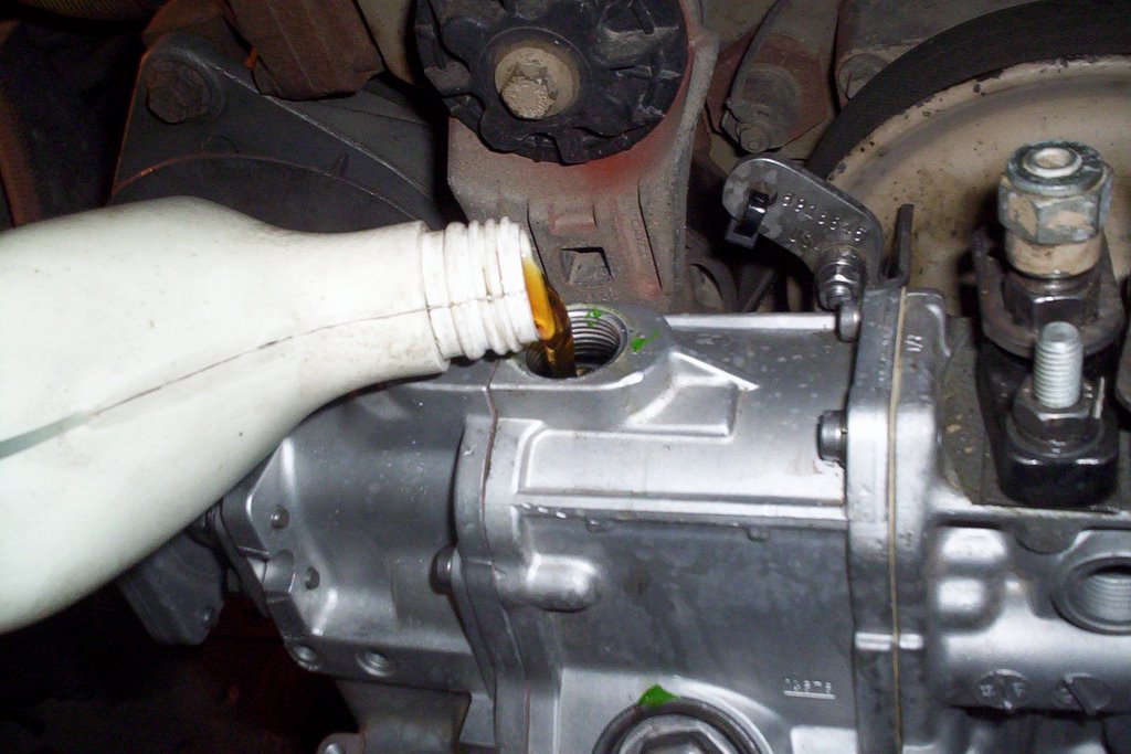
PRE-LUBE INJECTION PUMP:
When a repair has been made on these pumps they must be pre-lubed with engine oil. Remove top plug from the governor housing with an Allen wrench. This particular model requires .71 Litres [24 oz.] . Failure to do this could cause damage during start-up.
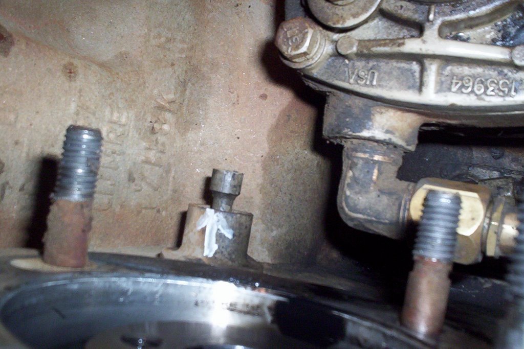

TIMING THE ENGINE:
The next step is to time the engine by rotating clockwise [viewed from the front] while pushing on timing pin until it engages into the camshaft gear. Engine is now properly timed, the fuel injection pump is ready to INSTALL.
 After the 4 mounting bolts are tightened, torque accessory drive gear retaining nut to 106 in. lbs. then DISENGAGE BOTH TIMING PINS. The injection pump timing pin just pulls out, flips around and stays installed on the pump for next time. The engine timing pin just pulls back and stays put.
TORQUE DRIVE GEAR RETAINING NUT:
Now it's time for the final torque 144 ft. lbs. NOTE: torque specs will vary depending on the injection pump model. Now it probably makes sense to you why it's important to disengage both timing pins. They will sheer off very easily being made out of plastic and debris will get into the injection pump housing or engine timing gear housing.

BLEEDING THE FUEL INJECTION SYSTEM:
Once the lines, linkages and accessories have been assembled it's time to bleed the system. Loosen bleeder plug located on the engine side of the injection pump. Operate transfer pump by hand until all air has been bled out of bleeder plug. Tighten bleeder plug.
Crack as many injector lines as you can at each cylinder and crank over engine until there is evidence of fuel at each injector. Stop cranking and tighten injector lines, start cranking engine once again and before you know it you'll have a smokin' diesel engine!
Sunday, January 09, 2011
No Start Cummins Diesel Engine
 Cummins Diesel Engine
Here are a few tips and checks you can make when your Cummins Diesel Engine will not start. This information pertains to mechanical injection diesel engines.
Don't feel insulted with some of these checks because the simplest steps have been overlooked many times.
The rule of thumb is Check The Simple Things First!
- When your Diesel engine cranks but will not start - No smoke from exhaust
- Is there fuel in the supply tank? Always check the source on your diesel engine
- Check electric or manual fuel shut-off.
- Is the air intake or exhaust plugged?
- Note: Remember, a diesel engine needs air and fuel to run
- Fuel filter plugged / seperator full of water?-drain as required.
- Your diesel engine injection pump not getting fuel or fuel is aerated. Check fuel flow or bleed fuel system.
- Check inlet restriction to fuel transfer pump
- Inspect lift pump operation. Remove outlet line and crank over engine
- Worn or malfunctioning injection pump
- Internal pump timing incorrect
- Engine camshaft out of time
Check the filters to see if they are still full of fuel, if not you've got a diesel engine that has run out of fuel - a no brainer. I went on a service call once and found out that the operator had filled the tank with gasoline, anything can happen!
Otherwise you have an obvious failure that you have to sink your teeth into. Replace fuel filters if the mileage or hours are excessive.
Check fuel lines from the tank to the primary filter [Fuel/Water Seperator]
Tip: I use a remote fuel container and slip the suction line before or after the primary filter. If diesel engine performance improves you know you have to start checking for faults back to the tank.
This procedure bypasses the fuel tank and lines up to that point which tells you if the problem exists in those areas i.e. restriction or split/cracked fuel line or bad pick-up tube in the tank.
Pull output line off of the lift pump on the side of the block and crank engine over and check for fuel output.
Prime fuel system with primer pump and bleed the injection pump, once primed crack injection lines at the injection pump and observe for fuel output.
In most cases you will find a problem up to this point, if not check injection pump timing or check to see if the camshaft gear is actually driving the injection pump. These failures are not common at all.
I hope these tips help you troubleshoot your Cummins Diesel Engine.
Friday, November 05, 2010
Cummins ISB Engine
For emission requirements the Cummins ISB engine was re-engineered to a 24 valve system. the acronym ISB stands for Interact System B with a Bosch VP44 rotary injection pump which was used until 2003. After 2003 it had an upgrade to a Bosch common rail high pressure injection system.
Torque was increased to 610 lb ft giving it higher low speed torque and a increased performance output compared to a V8 diesel in the medium duty truck industry.
5.9L Cummins ISB Engine Specifications:
The displacement is 5.9 Liters (359 cu. in.) with an inline 6 design. The firing order is 1-5-3-6-2-4 with a compression ratio of 16.3:1 and a high output version ratio of 17.2:1. Direct Injection started in 1998 which changed to common rail injection in 2003. The torque is 460 - 610 lb-ft @ 1,600 RPM with Horsepower rated at 235 - 325 HP @ 2,900 RPM.
From a Mechanic standpoint I really like the Cummins ISB engine and as you can hear from the video it really purrs nicely (After the compressor kicks out). The biggest problem we've had with the 2009 models is a minor exhaust manifold leak on a few of them and one compressor failure. In a fleet of buses that is an excellent record.
Friday, June 04, 2010
Cummins ISC Diesel Engine Fuel In Oil Repair.

The Cummins ISC Diesel Engine is a great performer, we have several in our fleet and they are a very durable diesel engine. As with any engine there are failures and in this case we experienced the oil level increasing to an over full condition. One test that told us it was fuel in the oil was the oil sample analysis. We took a sample and the guys at BTA in Kamloops faxed over a report to let us know it was in fact diesel fuel.
Another tell tale red flag was the oil pressure was dropping below normal along with a splatter of oil on the rear engine compartment door. The viscosity decreased making the oil thinner causing these conditions. We actually went through this repair before and the symptoms were exactly the same (that's what happens when you have a fleet with the same drive train).
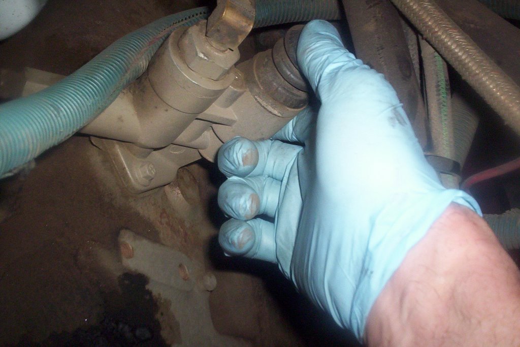
The CAPS Fuel Pump has to be replaced to repair this condition since it provides the high pressure fuel and injection delivery. It runs directly off the accessory gear and is about the same size as a 2 cylinder air compressor. The fuel lines and accessories have to be removed along with the pump accessory drive gear. The first thing to do after this repair is change the engine oil and get rid of that thinned out engine oil.
Friday, March 05, 2010
The Cummins Diesel Engine AfterTreatment System
Cummins Diesel Engines have developed an after-treatment system that is very compact and easy to maintain. The only requirement is to have Diesel Exhaust Fluid available to add to the holding tank which is supplied by the Original Equipment Manufacturer.
Take a look at an over view of this system. Our fleet will be getting into these systems since we're running Cummins ISB and ISC Diesel Engines. Technology never stops growing, the age of smoky and sooty old exhaust pipes have come to an end.
Frequently Asked Questions - Cummins Aftertreatment System
1) What makes up the Cummins Aftertreatment System?
There are four major components: Selective Catalytic Reduction (SCR) Catalyst, Decomposition Reactor, DEF Dosing Valve, Cummins Particulate Filter.
2) What is DEF (Diesel Exhaust Fluid)?
DEF is a 32.5% strength urea water solution.
3) How much DEF will be required?
DEF consumption is expected to be approximately 2% of fuel consumption dependent on vehicle operation – duty cycle, geography, ratings, etc.
4) What size DEF tank is required on a vehicle?
The vehicle manufacturer/OEM will determine exact tank size and location on the vehicle. However, Cummins will be providing installation recommendations to the OEMs on tank size selections.
For example, in Europe, vehicle SCR tank sizes are typically 15 – 20 gallons.
5) What happens if the vehicle runs out of DEF?
Vehicles in 2010 that will use DEF will have two indicators on the dash that will alert the driver to quantity of DEF on board. One, there will be a new DEF gauge very similar to a fuel gauge today that will indicate level of DEF (i.e. full, half, quarter, etc.) Second, there will be a new DEF low level warning lamp that will illuminate when less than 10% of DEF is in the tank.
If the vehicle is operated such that one would run completely out of DEF the vehicle will not be shut down; however, power will be reduced enough to encourage the operator to refill the DEF tank. Once the tank has been refilled the engine will resume normal power levels.Mechanic Information to live by...
Take a look at an over view of this system. Our fleet will be getting into these systems since we're running Cummins ISB and ISC Diesel Engines. Technology never stops growing, the age of smoky and sooty old exhaust pipes have come to an end.
Frequently Asked Questions - Cummins Aftertreatment System
1) What makes up the Cummins Aftertreatment System?
There are four major components: Selective Catalytic Reduction (SCR) Catalyst, Decomposition Reactor, DEF Dosing Valve, Cummins Particulate Filter.
2) What is DEF (Diesel Exhaust Fluid)?
DEF is a 32.5% strength urea water solution.
3) How much DEF will be required?
DEF consumption is expected to be approximately 2% of fuel consumption dependent on vehicle operation – duty cycle, geography, ratings, etc.
4) What size DEF tank is required on a vehicle?
The vehicle manufacturer/OEM will determine exact tank size and location on the vehicle. However, Cummins will be providing installation recommendations to the OEMs on tank size selections.
For example, in Europe, vehicle SCR tank sizes are typically 15 – 20 gallons.
5) What happens if the vehicle runs out of DEF?
Vehicles in 2010 that will use DEF will have two indicators on the dash that will alert the driver to quantity of DEF on board. One, there will be a new DEF gauge very similar to a fuel gauge today that will indicate level of DEF (i.e. full, half, quarter, etc.) Second, there will be a new DEF low level warning lamp that will illuminate when less than 10% of DEF is in the tank.
If the vehicle is operated such that one would run completely out of DEF the vehicle will not be shut down; however, power will be reduced enough to encourage the operator to refill the DEF tank. Once the tank has been refilled the engine will resume normal power levels.Mechanic Information to live by...
Monday, April 06, 2009
Cummins Diesel Repair - ISC Model
 This particular Cummins diesel repair was necessary because of an indirect code that was finally traced to the camshaft endplay. There are 2 sensors installed to the backside of the timing cover just below the top drive gear (the 2 black round shaped sensors are visible to the right of the cam shaft bearing bore). One is the camshaft position sensor the other is the engine speed sensor.
 To remove the camshaft the rocker arms and shafts must be removed first. The wooden dowels act as holding devices that jam into the solid lifters that ride on top of the cam lobes. Once the dowels are installed elastic bands are used to hold them secure while removing the camshaft. This saves a lot of time not having to pull the cylinder head.
 The camshaft endplay was excessive which caused the sensor problem/codes to become a regular occurrence. The first step we took was to change the sensors, this cured the problem for several weeks but the fault always came back to haunt us. The camshaft showed signs of wear on the shoulder where the gear sits and the cam lobes as well. There is a thrust washer that goes between the gear and the engine block to help with endplay movement.
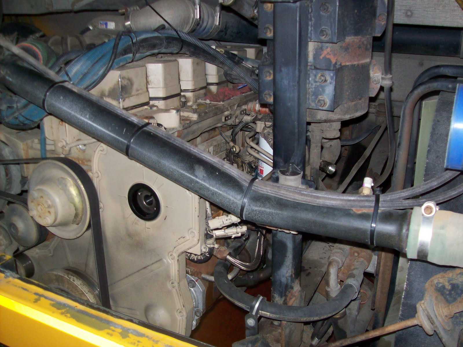
 If you have to do this job in a Thomas ER Pusher Bus you will have to remove the rear engine mounts and lower the engine enough to get the rear pushrods out of the engine. The solid floorboards above are not designed to allow the pushrods enough headroom for removal.
The cam gear has to be heated to 400 degrees Fahrenheit to install back onto the camshaft. We elected to replace the gear as well as the camshaft. If you are a Diesel Mechanic this is a Cummins Engine repair you may have to go through one day. I hope this mechanic info has helped you understand the procedures involved in this operation.
Subscribe to:
Posts
(
Atom
)