Wednesday, November 30, 2005

CUMMINS 8.3 litre DIESEL ENGINE HEAD GASKET REPLACEMENT... Reassembly and Valve Adjustment


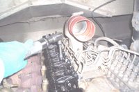
The injectors have been tested and ready for installation. Make sure the copper sealing washer is slid over the tip of the injector before installing, use a light grease to keep washer from sliding off the end. Once injector is slid into the bore of the head install injector hold-downs and retaining bolts. Torque to 18 ft. lbs. The injectors have been installed and torqued to specs. So the next operation is installing the air intake manifold and fuel injection lines. This is much easier with the rocker arm assemblies removed.
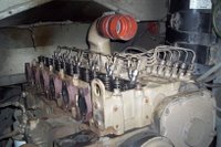
Four intake manifold bolts also serve as injection line hold-down bolts, torque intake manifold bolts to 18 ft. lbs. Once injection lines are tightened the fuel return lines can be fastened down with new copper sealing washers.

The rocker arms and pushrods can now be installed and torqued to 41 ft. lbs. Don't forget the oil manifold that sits underneath the rocker arms, it sends lubricating oil to the rocker arms and shafts.
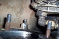
Bar engine over until timing pin engages with the camshaft gear, the engine is now on #1 cylinder Top Dead Center on the compression stroke. Timing pin is located under the injection pump.
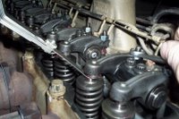
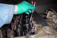
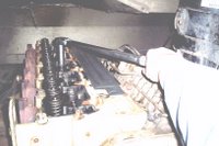
The Intake valves are adjusted to .012 while the Exhaust valves are adjusted to .024 clearance. The valves are Intake then Exhaust on each cylinder looking from the front of the engine.

On #1 cylinder Top Dead Center Compression stroke adjust #1 #2 #4 intake valves and #1 #3 #5 exhaust valves.

Rotate engine 360 degrees [remove timing pin first]

Adjust #3 #5 #6 intake valves and #2 #4 #6 exhaust valves

Roll the engine around again and re-check valve adjustment.
Tuesday, November 29, 2005

CUMMINS 8.3 litre DIESEL ENGINE HEAD GASKET REPLACEMENT....Torquing Down The Head Bolts


With the block and head cleaned and inspected, lay down the new head gasket and place the head carefully on to the engine block, lining up the 2 dowels on top of the block. The 5 rear pushrods were set-up the same way as before when we removed the head [This is for Thomas school buses only]


The exhaust manifold was left off to allow an even lift with the hoist. There are 26 head bolts in total and they must be checked for pitting and bolt stretch. The head gasket kit comes with a guage that you can check each head bolt with. If the bolt hits bottom on the guage this means the threads have been stretched out. These head bolts must be discarded.


Apply a light film of engine oil on the head bolt threads and install them in the head bolt holes. Torque each head bolt to 52 ft. lbs. starting from the middle and working your way out in a circular motion. Re-torque head bolts a second time.


Torque the 14 LONG head bolts in the middle to 105 ft. lbs. Recheck torque

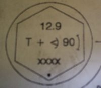
Cummins uses a torque and turn method that works well to compensate for thread stretch and gives a more accurate final torque. The top of each head bolt has the above markings signifying a torque and turn head bolt.

Once the head bolts have been torqued to specs. each head bolt must be advanced another 90 degrees. Just mark a spot on top of the head and turn each head bolt one and a half hexes since each hex is 60 degrees. The head bolt is pre-marked with a reference point as shown above.

When the head bolts are finally torqued, the injectors, fuel lines, rocker arms/pushrods and intake manifold can be installed. Valve adjustment comes next.............

Monday, November 28, 2005

CUMMINS 8.3 litre DIESEL ENGINE HEAD GASKET REPLACEMENT Continued...Removing the head


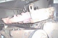
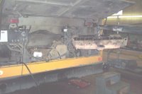
Once all the head bolts have been removed it's time to pull the head. I mentioned in an earlier post that the Thomas school buses have very little headroom at the rear of the engine.

Originally we used to pull the engine front crossmember and engine mount allowing us to lower the front of the engine providing enough clearance to remove the rear pushrods. That took a lot of time so eventually we thought of a better idea.

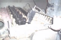
Using tie straps we suspended the last 5 pushrods in the head so when the head was lifted high enough, the bottoms of the pushrods would clear the block.

The picture above demonstrates this technique saving hours of labour compared to the old front crossmember technique. The exhaust manifold has been left on giving the head a bit of a tilt providing more clearance for the pushrods.

There you have it, the head and engine block can now be cleaned up and inspected. Look for cracks and unusual wear on both machined surfaces of the cylinder head and engine block. If uncertain it's advisable to send the cylinder head out to a machine shop who specializes in heavy duty diesel engines.

The top of the block and cylinder head can be checked with a straight edge to find any uneven surfaces. Check for pitting especially where the failure in the head gasket occurred.

In this case there was a coolant leak from the rear of the head gasket that allowed coolant to run down the back of the engine which we eventually spotted. We've done a number of leaking head gasket repairs on the Cummins 8.3 but usually after extended running time and mileage.

To be continued....

Wednesday, November 23, 2005

CUMMINS 8.3 litre DIESEL ENGINE HEAD GASKET REPLACEMENT Continued....Disassembling Head

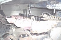
With the turbocharger removed the next step is to remove the rocker arms and pushrods. There is also an aluminum oil manifold that sits underneath each rocker arm. A Cummins diesel engine installed in a Thomas school bus has mimimal clearance at the rear so the last 5 pushrods cannot be removed yet. There is a technique we use that's simple and saves time, I'll demonstrate this in my next post. Once the rocker arms are removed it's much easier to take off he injector fuel lines. They must be removed completely, along with the return lines. There is a manifold at the fuel filter head, the banjo fittings must be removed there as well. Remove the fuel line hold-down bolts which are also the intake manifold mounting bolts. Remove intake manifold.

The injectors MUST be removed before taking off the cylinder head to prevent damage to them. After removing injector hold-downs remove injectors with a suitable puller. The exhaust manifold may be left on for convenience. Remove all of the cylinder head bolts. I usually CRACK them loose by hand and use a 3/8 air ratchet where accessibility is limited. The cylinder head is ready for removal.

That will be shown in my next post....


CUMMINS 8.3 litre DIESEL ENGINE HEAD GASKET REPLACEMENT...Removing accessories

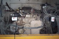
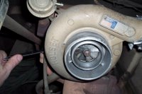
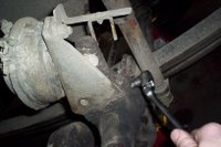
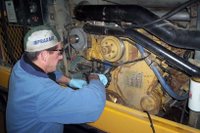
This Cummins 8.3 diesel engine is in a Thomas school bus so accessibility is different compared to working on a highway truck. The Cummins 8.3 head gasket here is leaking down the back of the engine, so draining the coolant and removing the piping and hoses is the first step. The coolant drain petcock is located at the bottom of the engine oil cooler. This will drain enough coolant to allow removing the head without massive coolant loss onto the shop floor. The turbocharger can come off next, remove exhaust, charge air and intake piping then oil drain hose, oil pressure line and 4 retaining nuts. All diesel engines have turbochargers to supply boost air to the intake system, this particular unit is a HOLSET model, typical for Cummins diesel engines.

TO BE CONTINUED.....

Tuesday, November 15, 2005

HOW TO CHANGE A WHEEL SEAL ON A STEERING AXLE - THOMAS SCHOOL BUS.

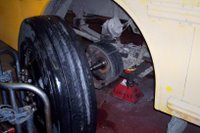
This procedure applies to any heavy duty truck steering axle. This particular axle is manuactured by EATON Corp. Raise up front end and set steering axle down on appropriate floor jacks and back off brakes.

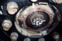
With drain pan in place remove oil hub cap, cotter pin, wheel bearing adjusting nut and washer.

Remove wheel and hub assembly with proper wheel jack and clean out gear oil in wheel hub.

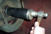
To remove wheel seal it's necessary to use a punch, striking inner bearing which eventually pops the seal out of the hub. When hitting bearing make sure punch strikes against the INNER bearing race to avoid damage to the bearing cage.

Our shop uses STEMCO wheel seals which have a wear ring that's installed on the axle shaft. To remove the wear ring I use a bushing splitter tool. Another method is to peen the outside of the ring with a ball-peen hammer which expands the ring diameter causing it to slide off the axle shaft easily.
Using the proper tool, install new wear sleeve making sure the edge is flush on axle shoulder.

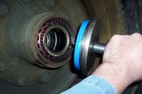
After cleaning and inspecting wheel bearings pre-lube with 80w90 gear oil. Using seal installation tool, drive new seal into hub until it bottoms.

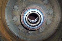
The inner bearing and wheel seal is now properly installed and ready for the next step.

Using a wheel jack install wheel and hub assembly back onto steering axle, being careful not damage seal in the process. Having the brakes backed off makes this step much easier.

Fill the hub with 80w90 gear oil before installing outer wheel bearing which should be pre-lubed as well.
Tighten wheel bearings while rotating wheel, this will seat bearings properly. Back off and torque to 25 foot pounds lining up cotter pin hole at the same time.

NOTE: I've been using this bearing torque spec. for years and have never had a problem.

It's easier this way since the alternative method was by feel or to visually check to see if all the bearing rollers on the outer bearing were turning evenly. It doesn't hurt to double check with the latter method if you want to make double sure the bearings are adjusted properly.

On the drive axles I torque the wheel bearings to 50 ft. lbs. and the outer locking nut to 250 ft. lbs. These specs. were provided by the CARLISLE Brake Organization.

Install NEW cotter pin and bolt up oil hub cap and fill with 80w90 gear oil until proper level is reached.
Lastly, re-adjust brakes and check opposite wheel adjustment to make certain brakes are adjusted evenly. ON THE ROAD AGAIN!


RECOMMENDED READING:

  • Motor Oil & Filtration

  • Trust My Mechanic
  • Sunday, November 13, 2005

    CHANGING A WATER PUMP ON A CAT 3116 DIESEL ENGINE


    We have 13 Caterpillar 3116 diesel engines in our school bus fleet, a well built engine with a unique fuel system, unit type injectors connected to a rack mechanism that's controlled by a governor. However they do have a weak spot, namely the exhaust valves.

    There have been a few instances of a dropped valve in the cylinder head [the exhaust valve breaks to pieces] this causes damage to the piston and head. So off comes the head for exchange and our 'fingers are crossed', hoping for minimal damage to the cylinder walls and turbo. That story may surface in a future posting.
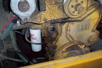
    Water pump replacement is an easy job, as you can see it's located at the front of the engine. This 3116 is in a Thomas ER model [pusher] school bus.
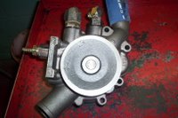
    With coolant drained, remove idler pulley, hoses, drive belt and 4 retaining bolts. Water pump is now ready for replacement with the exchange unit.

    NOTE: The water pump belt runs on an idler pulley that's used to adjust belt tension. Check the idler pulley bearings and the pulley for wear. We've had some bearing failures in the past but now we make a point of checking them on a regular basis. The bearing itself is easy to replace and common enough to be found at any bearing distributor.The Cat distributor can get us a reman water pump overnight but in this case we stock one at all times because of this recurring failure. The most common problem is the bearing seal which causes a coolant leak out the pump body just behind the pulley.

    Once reassembled we do running checks before releasing the bus. The best way to purge the air out of the cooling system is taking the bus for a good roadtest to allow the thermostat to open fully.

    These school buses have approxiamately 18 to 20 litres of coolant in the cooling system running through 1 inch heater hoses to numerous interior heater cores. So there are lots of pockets of air when the coolant is totally drained.


    RECOMMENDED READING:

  • Motor Oil & Filtration

  • Trust My Mechanic
  • Friday, November 11, 2005

    What Is Multi-Grade Engine Oil?

    The Society of Automotive Engineers is a professional organization and standards body for the engineering of powered vehicles of all kinds - cars, trucks, boats, aircraft and more.

    The SAE designation for multi-grade oils includes two grade numbers; for example,10W-30 is the designation for a common multi-grade oil. The first number associated with the W, the 10, means that the viscosity of this multi-grade oil at winter temperature corresponds to the viscosity of a single-grade 10W oil at winter temperature.

    The second number, 30, means that the viscosity of this multi-grade oil at hot operating temperature corresponds to the viscosity of a single-grade 30 oil at the operating temperature. The motor oil grade to be used in a given vehicle is specified by the manufacturer of the vehicle.

    VISCOSITY is the resistance to flow of a fluid. As an example, water flows easily so it will have a low viscosity [a low resistance to flow] while cooking oil has a high viscosity [a high resistance to flow]

    Here's The Bible On Motor Oils

    Wednesday, November 09, 2005

    Installing Fan Over-ride Switch On A Thomas School Bus With 3116 Cat Engine


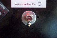
    Our buses [between 1995 & 1998] with 3116 Caterpillar diesel engines overheat in hotter ambient temperatures 30 degrees Celsius and up [90 degrees Fahrenheit]. They come with the same components as the Cummins equipped school buses but they reach very close to shutdown levels @ 220 degrees. After trying everything to cure the problem we decided to install a engine cooling fan over-ride switch on the dash. The operator just flips it on before climbing a steep grade just to get a jump start on the engine cooling process.


    The engine fan motor is hydraulically actuated and electrically controlled by a coolant temperature switch [shown above]. When engine temperature reaches 200 degrees the coolant switch opens creating an open circuit. The engine fan is now rotating at engine RPM maximizing it's cooling potential.


    The dash switch is wired in between the sensor wire and the sensor in series, and that's all there is to it. When the switch is flipped to the open mode you are creating an open circuit which turns the engine fan ON full blast.
    The operator who usually drives the same school bus everyday knows his or her bus and it's habits. So he or she knows when to flip the fan switch. It may be a band aid solution but it works! After fighting the problem for a long time futility sets in and sometimes it's not a bad idea to IMPROVISE!

    RECOMMENDED READING:

  • Motor Oil & Filtration

  • Trust My Mechanic
  • Tuesday, November 08, 2005

    WHAT IS BIODIESEL?

    Biodiesel is fuel made from renewable resources such as vegetable oils or animal fats. It is biodegradable and non-toxic, and has significantly fewer emissions than petroleum-based diesel when burned. Biodiesel functions in current engines, and is a possible candidate to replace fossil fuels as the world's primary transport energy source.

    With a flash point of 150°C, Biodiesel is classified as a non-flammable liquid by the Occupational Safety and Health Administration. This property makes a vehicle fueled by pure biodiesel far safer in an accident than one powered by petroleum diesel or the explosively combustible gasoline. Precautions should be taken in very cold climates, where biodiesel may gel at higher temperatures than petroleum diesel.

    Biodiesel can be distributed using today's infrastructure, and its use and production is increasing rapidly (especially in Europe, the United States, and Asia). Fuel stations are beginning to make biodiesel available to consumers, and a growing number of transport fleets use it as an additive in their fuel. Biodiesel is generally more expensive to produce than petroleum diesel, although this differential may diminish due to economies of scale and the rising cost of petroleum.

    RECOMMENDED READING:

  • Motor Oil & Filtration

  • Trust My Mechanic
  • CHANGING A FAN BELT ON A MERCEDES MBE 900 DIESEL ENGINE.


    Changing the fan belt on a Mercedes MBE 900 diesel engine is pretty basic stuff considering all the other possible repairs. The fan belt however is very important considering what it does for the engine and what could happen if it failed. The alternator would quit charging, causing an electrical system shutdown and the engine would eventually overheat causing an even bigger problem! So when you think about how important the fan belt really is it's essential to check it closely during maintenance checks.


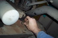
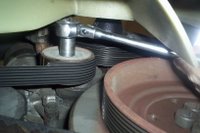
    The Multi-ribbed belt [8 ribs] has a tensioner that keeps the belt tight. This is a normal design for most modern diesel engines. The only disadvantage is getting at the tensioner with a wrench or socket to relieve tension on the belt enough to remove it. In this case with the Mercedes diesel, I found getting at the tensioner from underneath to the be the easiest method.


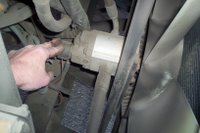
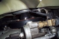
    Looking down on the fan assembly you'll see a electrical connection and wiring along with a fibre strap that's bolted to the fan hub and engine block. The wiring harness feeds the power supply to the fan clutch which comes on fully when the engine reaches peak engine temperature. The fan becomes' locked on' and rotates at engine RPM , a 1:1 Ratio. This maximizes the engine fan cooling capacity. The exact opposite occurs with a cold engine, less fan rotation helps to speed up the diesel engine warm-up.


    In order to slide the fan belt out from around the fan hub this strap must be removed temporarily. Remove the single bolt on the block securing the strap and disconnect harness. Pull assembly out of the way so fan belt may be removed.

    Install new belt with reverse procedure. This is not a hard job, but I've seen what a broken fan belt will do to a diesel engine if not detected immediately! It's much easier in the long run to check fan belts carefully and.... If in doubt change it out!!

    RECOMMENDED READING:

  • Motor Oil & Filtration

  • Trust My Mechanic
  • Friday, November 04, 2005

    AUTOMATIC TIRE CHAINS ARE WORTH THE COST!


    Our School Bus fleet uses automatic tire chains made by a company called ONSPOT. They are used on buses that run in severe winter conditions and get two thumbs up from our drivers.


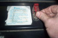
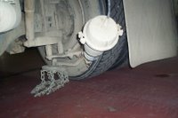
    Turning on the auto chain switch energizes a solenoid that directs air pressure instantly to the actuating air chambers.

    The photo above shows the electric solenoid. A 12 volt supply comes from the dash switch energizing the solenoid. This allows reservoir air pressure out through the application air lines, actuating the ONSPOT chainwheel arms.


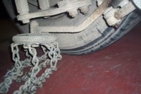
    The auto tire chains are now in the applied position as shown above. There are some special installation instructions that must be followed to ensure proper operation.
    • chainwheels are color coded: RED for the driver side and BLUE for the passenger side
    • the chainwheel should contact the tire at the vertical centerline of the tire
    • the pitch of the chainwheel should be O to -1 degree
    • operating angle should be 8 to 15 degrees
    • vertical distance from the ground to the chainwheel contact point should be 3 1/2 to 4 in.

    Auto chains work very well and parts are easily accessible. Having a School Bus fleet means making sure the pupils get to school and back home again. Auto chains make our job easier with less worry and service calls. For winter driving these chains are invaluable!

    For more information checkout Onspot.com


    RECOMMENDED READING:

  • Motor Oil & Filtration

  • Trust My Mechanic
  • Thursday, November 03, 2005

    CUMMINS 'C' INJECTION PUMP REMOVAL

    We have several Cummins diesel engines in our school bus fleet, the most common being the 'C' model. This diesel is an in-line 6 with an 8.3 litre displacement.
    They have been a very reliable engine with only minor problems like oil leaks and the odd head gasket failure.
    Our newer buses have the ISC Cummins engines, an electronic version of the older 'C' models. The main reason for going electronic is to control emmissions. Software and a laptop computer is required to analyze the ISC.


    Cummins 'C' model diesel engines use a BOSCH inline fuel injection pump. A common fault is oil leaking out the shutdown shaft seal but on this engine a major failure occurred. The mainshaft broke in the pump causing a definite no run condition. This type of failure is a 'first' for our fleet.

    The first step is to remove the front plug, allowing access to the injection pump accessory drive gear retaining nut.
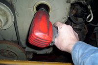
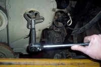
    Remove the retaining nut with an impact gun and 15/16 impact socket.


    Using a suitable puller, remove the injection pump drive gear. The shaft is tapered so there will be a sudden release of the gear from the shaft.


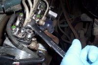
    Remove injection lines, fuel supply and return lines, fuel shutdown solenoid, throttle linkage, air/fuel control piping and 4 mounting nuts.


    Injection pump is now ready to remove, carefully pull back complete unit & lift out. TIP: The 2 inner mounting nuts between the engine block and pump body are hard to get at, a 15mm 3/8 drive swivel socket and long extension[s] will make removal much easier.

    Our shop does not get into major repairs on these injection pumps, we deal with a reputable fuel injection repair shop who have the tools and equipment required to repair and test these units properly.


    RECOMMENDED READING:

  • Motor Oil & Filtration

  • Trust My Mechanic