Saturday, July 29, 2006

Diesel Mechanic - International DT 466E Valve Adjustment

DIESEL MECHANIC - How To Adjust Valves On An International DT 466E Diesel Engine


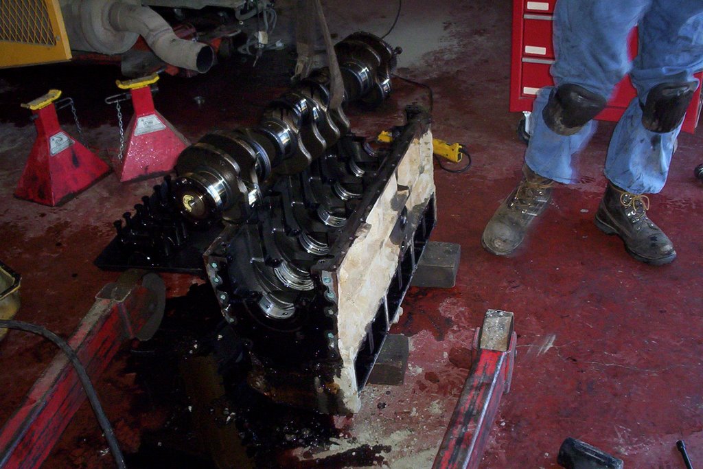
The DT 466E diesel engine is the electronic version of the former DT 466. This an engine we diesel mechanics all know and love since they are virtually almost bulletproof with a fantastic performance record. With emissions standards here to stay International has followed the other engine manufacturers and engineered electronic injection into their design.

The hardest part about working on these diesel engines is getting to the components, especially the valves if it's time for adjustment. The air to air piping has to be removed as well as the doghouse cover from inside the cab followed by the electronic control unit. These steps are required just to be able to reach the valve cover bolts.

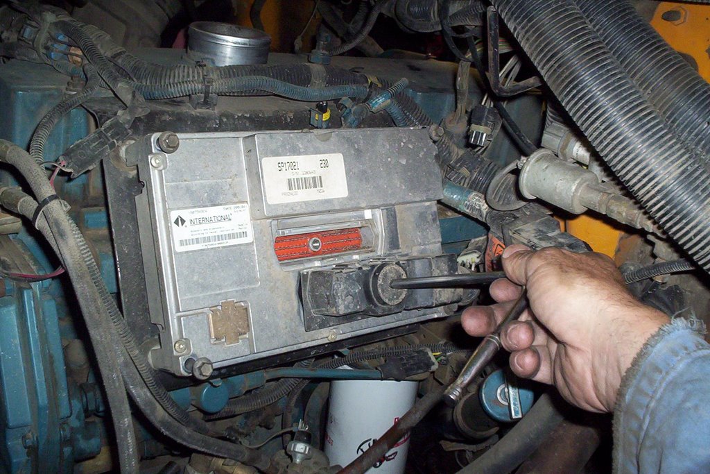
Remove the multi-pin connectors at the ECU [electronic control unit] with a 1/4 inch drive ratchet. Remove the round connector going into the valve cover housing.


Remove the 4 bolts holding ECU to the support bracket using a 10 mm socket. Remove ECU and take care it's an expensive component!


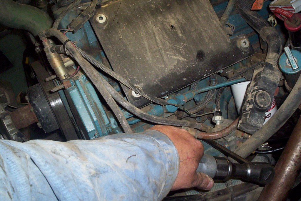
Remove ECU support bracket, there is a larger fastener below bolted to the block and 4 valve cover studs at the top side where you have to remove four retaining nuts.


Push the ECU harness connector into the valve cover housing as it will stay with the injector wiring when removing cover.


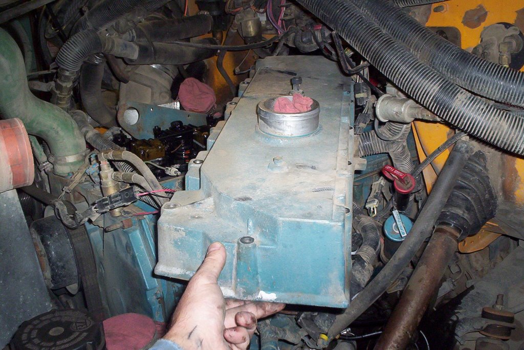
Remove valve cover, the weight has increased drastically compared to the original non-electronic engines because of the integrated intake manifold that is now part of the valve cover.

Rotate engine until TDC [top dead center] is achieved. There is a notch on the serpentine belt pulley behind the vibration dampner. An arrow and the letters TDC has been cast right into the front cover. Once lined up, the engine valves will be on #1 TDC compression or exhaust stroke.

An easy way to tell is if #1 cylinder valves are both loose and #6 cylinder valves have no clearance, then you know you are on #1 compression stroke. Note: There are 12 valves in total #1 valve being at the front while #12 valve is the last valve at the rear of of the cylinder head.

So if I say adjust #4 valve you just count from the front of the head, the first valve being #1. This makes it easier to explain which valves to adjust.

On #1 TDC compression stroke adjust adjust valves #1 #2 #3 #6 #7 #10 . The valve clearance for both intake and exhaust is .025 in. preferably with the engine cold but that's not overly crucial.

Rotate engine 360 degrees the engine is now on #6 TDC compression stroke. Adjust #4 #5 #8 #9 #11 #12 valves.

Once you have all the valves adjusted you reverse the disassembly procedure and torque the valve cover bolts to 13 ft. lbs. and the 1/4 drive wiring harness connectors at the ECU to 35 in. lbs. The valve cover gasket is reusable but still inspect it for damage or indications of wear.

I hope this helps you out when it's time to adjust valves on your DT 466E Diesel Engine.


Diesel Mechanic

Wednesday, July 26, 2006

Rebuilt Starter - Delco Remy Model 37mt

Rebuilt Starter : How It's Done.


Delco Remy Starters can be serviced and repaired very easily as you will soon see. For a lot of today's shops the time it takes to disassemble and service/repair a starter isn't economical.

The customer wants to get his vehicle going and gone so when you add up the shop rate plus down time it's cheaper [most of the time] to install a remanufactured starter.
But, a lot of starter defects are very minor like water and dirt, worn brushes or a defective solenoid.

Since my job is to save money the way to go is Preventive Maintenance considering we have 70 School Buses in our fleet. We usually service our starters once a year to prevent breakdowns. The following is a step by step procedure our shop follows to check over a Delco Remy 37mt Starter.
This starter model is used in our DT 466 and Cat 3116 Diesel engines.

Remove the 6 torx head bolts holding the drive gear housing, use a T 40 Torx male socket.


Remove the nose housing which is secured by an o-ring to prevent water and other contaminants to enter housing.

Remove the expandable lock ring and lock washer. The lock washer fits over top of the ring with a chamfered shoulder that keeps the ring in place.


Remove the backside housing using an E8 external socket. The ground stud stays with brush holder after removing 1/2 inch nut.

Remove the 2 Positive brush fastener screws with a 1/4 inch socket. There are 2 positive brushes and 2 negative brushes, the positive brushes are wired into the motor windings.


An easy way to suspend the brushes is to lock them in place using the retainer spring. Pry each brush upwards until the spring can apply side pressure.

Remove brush holder assembly and check the condition of the brushes. We have a no flash contact cleaner that works great to clean up the brush holder.


Slide armature out of the drive gear from the opposite end then carefully slide out of the main motor housing.


Clean up starter armature in the lathe and follow up with sand paper for a nice finish. Just skim the surface when machining. Note: emery cloth is Ok to use but just blow off the armature after sanding and make sure the seperators between the commutator bars are clean.


Check solenoid for severe burn marks on contacts. The 2 threaded brass contact bolts can be turned 180 degrees to utilize unused side of contact surface. Check contact plate for pitting and clean up with emery cloth or replace.

These small parts are very affordable to replace, but like I said at the beginning of this post labor time is much longer than straight replacement of the starter.

Now that you know how to disassemble this starter you can easily put it back together. Once reassembled be sure to bench test the starter just for insurance that nothing has been overlooked.

Now you have yourself a Rebuilt Starter.

Sunday, July 23, 2006

Alldata Online Automotive Manual Review


Alldata
is an online automotive repair manual I have been using for quite some time now and I must confess I give it a 2 thumbs up. If you have any vehicle between the years 1982 and 2004 Alldata will have everything under the sun that was ever written about that vehicle.

The only models not supported by Alldata is North American Honda and BMW who asked not to be included.

So what kind of information does
Alldata
supply?
  • Technical service bulletins
  • Factory Recalls
  • Tune up and repair specifications
  • Diagrams and repair instructions
  • Factory repair times
  • Diagnostic trouble codes and how to troubleshoot them
  • Fluid capacities and specifications
  • Torque specs and more!

So what about those in print manuals we are so used to? I personally do not use them any more because of the convenience of Alldata being available online 24 hours a day from any computer.

All information can be easily printed out to take with you when making repairs. The biggest advantage is Alldata updates information every three months to stay current.

So for the Mechanic on the go and car owners I highly recommend:
The Alldata Online Repair Manual

Wednesday, July 05, 2006

Cat 3116 Diesel - Engine Removal

This CAT 3116 Diesel Engine has failed because of an exhaust seat on #5 cylinder that collapsed and the fragments caused damage to the cylinder wall. The next operation is to remove the engine assembly and strip down the block so the cylinder can be repaired.


The Cat 3116 block deck surface has to be secured with a special plate fastened down with head bolts so the block does not warp while boring is performed.
Here you can see the scores running down the cylinder wall. Bits of broken metal that came from the exhaust valve seat lodged between the piston and cylinder. The turbo will have to be sent out for repair as well since the failure was on the exhaust side. Fragments will have went through the turbine wheel[exhaust side of the turbo] which runs on a very close tolerance.


Once the block is standing up resting on the flywheel housing the pistons are easily removed. All accessories have been removed including the oil cooler, governor, front gear housing ,camshaft and follower assemblies.
The cylinder head was removed while in the bus frame. We built a lifting bracket to fit over 2 head bolt holes and picked up shorter grade 8 bolts so the block could be hoisted out of the frame.


Once the pistons, flywheel housing and main bearing caps have been removed we used a fibre lifting strap to hoist out the crankshaft.


Out comes the crankshaft and the block will be sent to the machine shop for repair. They will measure the cylinder wear and see if they can machine damaged cylinder and press a dry sleeve bringing #5 bore back to standard.
They will hot tank the block and later press in new camshaft bushings.
Stay in touch with this blog as I reassemble our CAT 3116 Diesel Engine.