Showing posts with label allison 3000 codes. Show all posts
Showing posts with label allison 3000 codes. Show all posts
Tuesday, June 16, 2015
Allison 3000 Automatic Transmission Turbine Sensor Replacement
Allison 3000 Automatic Transmission Turbine Sensor Replacement requires removing the bottom module of the transmission using a transmission jack. The module weighs around 50 pounds so it's much easier to lower it down easily while feeding the harness through the access hole in the transmission housing.
The turbine sensor is internal and is easily replaced once the module is exposed. This code is not very common but it was plain as day when hooked up to Allison DOC software. You can view a graph while road testing and the turbine sensor communication dropped out while on the road. There are 3 sensors on the Allison 3000 models. The engine speed sensor, output speed sensor and turbine sensor.
All these sensors have to be working properly for the transmission to shift properly. They can be tested using an ohm meter. Depending on the ambient temperature the reading should be around 300 ohms. The video gives you an idea on what the module looks like when removed from the main body and where the turbine speed sensor is located.
The 3000 series are very durable and most of the problems were in the wiring. The plastic convoluted loom that the harness is wrapped in is deadly on the wiring insulation. Through time vibration causes the loom to rub on the wiring and eventually expose the copper wire to the atmosphere. Years ago we would run new wiring to a sensor because of the resistance caused by exposure to the elements.
The special wire was twisted and shielded that fixed a lot of communication problems, Using the Pro Link was the first tool available for troubleshooting. Now Allison Doc software is the only way to go. Also I have to give a plug to synthetic transmission oil which in the past I refused to accept because of the price.
Believe me it's well worth the extra cost. Our mechanical failures are non-existent since using synthetic oil. It lasts longer and does not break down in the heat. Our services are 3 years between oil changes. You can't beat that when in our case we're running 77 school buses.
Getting back to our turbine sensor code repair. When removing the module I want to point out that you need to remove the 32 fasteners by hand. The aluminum threads in the housing wear out..... especially the filter housing retaining bolts. It isn't a fun experience heli coiling the threads on these units. We have a Kent Moore tool jig to re-thread the holes which is the only way to do it. I use a speed wrench to remove and replace the bolts.
I hope you enjoy the video and please make a comment and share this post. Cheers!


Friday, January 16, 2015
Allison 3000 Series Automatic Transmission Turbine Sensor Code Repair
The Allison 3000 series automatic transmission or the older label "MD3060" in my opinion is an excellent design. The modules come off one at a time and they are really quite easy to work on. You need the right tools and manuals of course but gone are the days of balls, springs and extra assembly parts that were common with older auto transmissions.
The photo below reveals the turbine sensor which is internal. The bottom of these transmissions have an aluminum cast unit called the control module. It has all of the solenoids and valve body that controls shifting. The code we had was a turbine sensor which stopped working only at certain times during a bus run. The turbine sensor being a winding which delivers the turbine speed signal to the transmission control unit was failing when the oil temperature got to a certain level.
Click on Each Photo to Enlarge

Using the Allison DOC software we were able to go on a road test and observe the turbine speed sensor and exactly what it was doing. The graph you see below in the photo show the activity of the output speed, engine speed and turbine sensors. These three signals are what the TCU reads to send the right information to the control module during operation for a proper shift at the right time and in the correct range.
Looking at the laptop image (click on the image to see more detail) you can see how great it is to be able to watch what the components are doing which makes it really easy to troubleshoot. What happened eventually when the transmission temperature got to around 140 degrees the turbine sensor flat lined on the graph reading causing the shifting to fail. At that time it was confirmed that the turbine speed sensor needed to be replaced and the labour to re and re the control module would not be wasted.

The control module is around 50 pounds so you need a tranny jack for sure. There are 2 dowels that line up the module to the main case and it's a bit of a fight prying the module down on to the jack. With some care it can be done including the removal of the wiring harness which slips through the access hole in the transmission case.
Once the sensor was replaced along with the necessary gaskets and seals the module was reassembled with new filters and sump suction filter (internal). The synthetic oil was added then running checks were performed. The road test was a success and the bus went back into service. Synthetic ATF oil is worth every penny in my book with anti foaming and heat resistant properties far superior than standard oils.

Valve body and shifting solenoids from the control module
Here is a link to the Mechanic's Tips Handbook in pdf form. It has very good general information with torque specs for servicing and other useful tips.
Monday, June 04, 2012
Allison Automatic Transmission Retrieving Codes
The Allison Automatic Electronic Transmission offers a quick method to retrieve trans codes without requiring the Pro-Link reader. This is for older models before Allison required shops to have the DOC software to have any hope finding out what the fault is.
The video above is all about a preset code which in this case is losing the "output speed sensor" signal to the Trans ECU. I unplugged the sensor connector and once you try to move forward the transmission defaults into 1st gear. Without an output speed signal the ECU does not know where the transmission output speed is at... so it goes into this mode to protect the transmission because of the programming set up by Allison.
The output speed sensor can be checked out with an ohm meter which averages around 350 ohms depending on ambient temperature. Of course the wiring and connections is a step that should not be ignored. Any kind of resistance in the 30 foot harness running to the driver's cab will give a false signal. Opens and shorts are possible as well since the wiring is exposed to the environment. CHECK OUT THESE PREVIOUS POSTS ON THE ALLISON 3000 SERIES AUTOMATIC TRANSMISSION
Tuesday, November 16, 2010
Allison Transmission Codes & How To Retrieve Them
If you have ever wondered about Allison transmission codes and what they mean or how to retrieve them....look no further. Read the explanation below and leave a comment here on this post and I will reply with the code details. This is the first procedure a Mechanic carries out when there is a transmission complaint.
How To Retrieve an Allison Transmission Code
With the key on run... press the 2 arrows on your shift pad. You will get a D1 then 4 digits after that. The 4 digit number is the code you're after. To check for more codes press "mode" and D2 will show up with the second code (4 digits). Press Mode again D3 will come up with the fourth code and so on.
For Example: A Speed Sensor code is 2214 2212 or 2223. There are various checks you can perform. If you have a code let me know and I will post detailed transmission code troubleshooting information to help you out.
Allison transmissions come in different series, the 1000, 2000 and 3000 series depending on the size of your vehicle. The electronics is labeled as WTEC 1, 2, 3 and now 4. These are generations of the electronic systems built through the years. WTEC 3 is very common for older trucks, the tell tale sign of this type of system is the 3 plug-ins at the Transmission ECU.
This is a quick overview of Allison Transmission Codes and will be followed with a video demonstration on how to retrieve codes. Newer WTEC 4 systems require software called Allison Doc using a laptop. The video will be focusing on a WTEC 3 system using the shift pad to get codes. If you're a Mechanic, owner operator or truck enthusiast this procedure is the first step to take if you run into problems.
Check out all my Allison Automatic Transmission posts HERE Full of Troubleshooting and Repair advice. Many faults can be repaired by running a new coaxial wire from the sensor to the ECU. If there is any interference or resistance issues with a signal to the ECU you will end up with a code.
UPDATE - VIDEOS DEMONSTRATING HOW TO RETRIEVE AND CLEAR ALLISON TRANSMISSION CODES USING THE SHIFT PAD.
Here are 3 quick videos I made on how to use the trans shift pad to find codes. I set up a code by disconnecting the output speed sensor at the transmission. This will demonstrate what happens when a fault code occurs and what you can do to find out which code it is and how to clear it.
Video 1 - I'm purposely setting a fault code by unplugging the output speed sensor at the transmission.
Video 2 - Retrieving the transmission fault code using the shift pad.
Video 3 - Hooking the speed sensor back up to simulate the repair being completed and clearing the code using the shift pad.
As you can see Allison transmission codes are easy to read and clear using the shift pad. At the very least you can find out what the fault is and relay that information to your mechanic or use it to troubleshoot the problem yourself. I had a service call once in the middle of the winter, the bus was stuck in 1st gear.
Sound familiar? What had happened was the connector and harness accumulated so much ice around it the weight actually pulled the connector out of the output speed sensor socket. That was weird but made for a happy ending. Another common code is '3500' which is the battery voltage feed to the ECU, battery voltage is hard wired to the ECU so if their is any interruption you're going to get that code number.
Please post your comments and questions below and I will get back to you. thanks!
CLICK HERE FOR THE ALLISON SHIFT SELECTOR OPERATION AND CODE MANUAL.
NOTE: This is for a 2009 4th generation Allison Transmission.
How To Retrieve an Allison Transmission Code
With the key on run... press the 2 arrows on your shift pad. You will get a D1 then 4 digits after that. The 4 digit number is the code you're after. To check for more codes press "mode" and D2 will show up with the second code (4 digits). Press Mode again D3 will come up with the fourth code and so on.
For Example: A Speed Sensor code is 2214 2212 or 2223. There are various checks you can perform. If you have a code let me know and I will post detailed transmission code troubleshooting information to help you out.
Allison transmissions come in different series, the 1000, 2000 and 3000 series depending on the size of your vehicle. The electronics is labeled as WTEC 1, 2, 3 and now 4. These are generations of the electronic systems built through the years. WTEC 3 is very common for older trucks, the tell tale sign of this type of system is the 3 plug-ins at the Transmission ECU.
This is a quick overview of Allison Transmission Codes and will be followed with a video demonstration on how to retrieve codes. Newer WTEC 4 systems require software called Allison Doc using a laptop. The video will be focusing on a WTEC 3 system using the shift pad to get codes. If you're a Mechanic, owner operator or truck enthusiast this procedure is the first step to take if you run into problems.
Check out all my Allison Automatic Transmission posts HERE Full of Troubleshooting and Repair advice. Many faults can be repaired by running a new coaxial wire from the sensor to the ECU. If there is any interference or resistance issues with a signal to the ECU you will end up with a code.
UPDATE - VIDEOS DEMONSTRATING HOW TO RETRIEVE AND CLEAR ALLISON TRANSMISSION CODES USING THE SHIFT PAD.
Here are 3 quick videos I made on how to use the trans shift pad to find codes. I set up a code by disconnecting the output speed sensor at the transmission. This will demonstrate what happens when a fault code occurs and what you can do to find out which code it is and how to clear it.
Video 1 - I'm purposely setting a fault code by unplugging the output speed sensor at the transmission.
Video 2 - Retrieving the transmission fault code using the shift pad.
Video 3 - Hooking the speed sensor back up to simulate the repair being completed and clearing the code using the shift pad.
As you can see Allison transmission codes are easy to read and clear using the shift pad. At the very least you can find out what the fault is and relay that information to your mechanic or use it to troubleshoot the problem yourself. I had a service call once in the middle of the winter, the bus was stuck in 1st gear.
Sound familiar? What had happened was the connector and harness accumulated so much ice around it the weight actually pulled the connector out of the output speed sensor socket. That was weird but made for a happy ending. Another common code is '3500' which is the battery voltage feed to the ECU, battery voltage is hard wired to the ECU so if their is any interruption you're going to get that code number.
Please post your comments and questions below and I will get back to you. thanks!
CLICK HERE FOR THE ALLISON SHIFT SELECTOR OPERATION AND CODE MANUAL.
NOTE: This is for a 2009 4th generation Allison Transmission.
Tuesday, November 02, 2010
Allison 3060 Automatic Transmission Fault Codes

The codes can be retrieved by pushing the 2 arrows at the same time (key on) to retrieve the 4 digit fault codes. Another method is to use the Pro Link Hand Held Reader. To clear the codes after you've repaired the problem hold the mode button until you hear 2 beeps. This has to be done during code retrieving.
Code 2511 means the output speed sensor has a zero speed reading. Check the speed sensor and connection, the ohm reading should around 300 ohms. Also check the ECU connectors. Make sure they are tight,clean and undamaged. Check the fluid level and check wiring to the sensor has no opens, shorts between wires or shorts to ground.
Code 2522 is related to 2511.... 22 being a sub-code.
Code 2312 is the shift selector. Check ECU for connectors, shift selector connector, check selector for proper operation and check the wiring harness for opens, shorts between wires and shorts to ground.
We have had lots of wiring issues and repaired a lot of these problems by running a new coaxial wire from the sensor to the ECU. There seems to be some resistance in the wire that causes improper signals to be relayed to the ECU.
Another area there has been faults is the shift selector pad. You can get a kit for the selector which isn't hard to replace.
If it's hard to push the selector to get into gear that's the first sign of trouble and a new selector pad would fix the problem. Here are all the posts I have produced on the Allison 3060 transmission with troubleshooting and repairs included. Scroll down and you will see some more Mechanic Information on the output sensor circuit.
Got Questions ? Please a comment..
Monday, October 25, 2010
Allison Automatic Transmission Troubleshooting MD 3060 Code 2116
The Allison automatic transmission MD 3060 is all electronic running off direct battery power to a series of relays, fuses and modules. The ECU (electronic control unit) for the transmission reads and controls inputs and outputs. Inputs include engine speed, output speed, turbine speed (the trans internal drive shaft) and throttle position. It computes these inputs into smooth shifts according to these variables.
The TPS Cable Complete - It's Located In The Engine Compartment Area

If it receives a bad signal everything goes to hell in a handbag. Code 21-16 is a trouble code for the Throttle Position Sensor. One of my newsletter subscribers from North Carolina has a 1996 Holiday Rambler motor home with a 5.9 Cummins diesel engine. He's dealing with this code and asked me to help him out.

The TPS control has 3 wires to it, one sends a 0 to 5 Volt signal to the ECU which regulates shifting patterns using these voltage readings. Full throttle and idle can be determined this way, if the wrong reading is sent then you will get a hard shifting scenario.The other 2 wires are the battery voltage and ground.
21-12 Code indicates that the ECU is receiving 14 counts or less. The TPS works with counts and 14 is too low so the problem might be at the closed throttle end of the TPS travel. The first check to make is the cable for frayed wires hanging up somewhere or a bad wire in the 3 wire harness.
My Crude Wiring Diagram Showing The Simplicity Of The TPS Circuit.
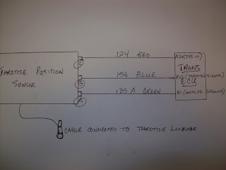
I've seen a couple of bad cables and have also replaced all three wires from the TPS to the Trans. ECU. You can check the wires for grounds, shorts or open circuits. If you replace the TPS you can reset it by cycling the ignition 5 times to reset the 0% and 100% throttle position or use the 'ProLink' Reader to reset the system.
The TPS Cable Complete - It's Located In The Engine Compartment Area

If it receives a bad signal everything goes to hell in a handbag. Code 21-16 is a trouble code for the Throttle Position Sensor. One of my newsletter subscribers from North Carolina has a 1996 Holiday Rambler motor home with a 5.9 Cummins diesel engine. He's dealing with this code and asked me to help him out.

The TPS control has 3 wires to it, one sends a 0 to 5 Volt signal to the ECU which regulates shifting patterns using these voltage readings. Full throttle and idle can be determined this way, if the wrong reading is sent then you will get a hard shifting scenario.The other 2 wires are the battery voltage and ground.
21-12 Code indicates that the ECU is receiving 14 counts or less. The TPS works with counts and 14 is too low so the problem might be at the closed throttle end of the TPS travel. The first check to make is the cable for frayed wires hanging up somewhere or a bad wire in the 3 wire harness.
My Crude Wiring Diagram Showing The Simplicity Of The TPS Circuit.

I've seen a couple of bad cables and have also replaced all three wires from the TPS to the Trans. ECU. You can check the wires for grounds, shorts or open circuits. If you replace the TPS you can reset it by cycling the ignition 5 times to reset the 0% and 100% throttle position or use the 'ProLink' Reader to reset the system.
Subscribe to:
Posts
(
Atom
)