Showing posts with label mechanic shop. Show all posts

Friday, December 31, 2010

Valve Adjustment On A DT466E International Diesel Engine

DIESEL MECHANIC - How To Adjust Valves On An International DT 466E Diesel Engine


The DT 466E diesel engine is the electronic version of the former DT 466. This an engine we diesel mechanics all know and love since they are virtually almost bulletproof with a fantastic performance record. With emissions standards here to stay International has followed the other engine manufacturers and engineered electronic injection into their design.

The hardest part about working on these diesel engines is getting to the components, especially the valves if it's time for adjustment. The air to air piping has to be removed as well as the doghouse cover from inside the cab followed by the electronic control unit. These steps are required just to be able to reach the valve cover bolts.
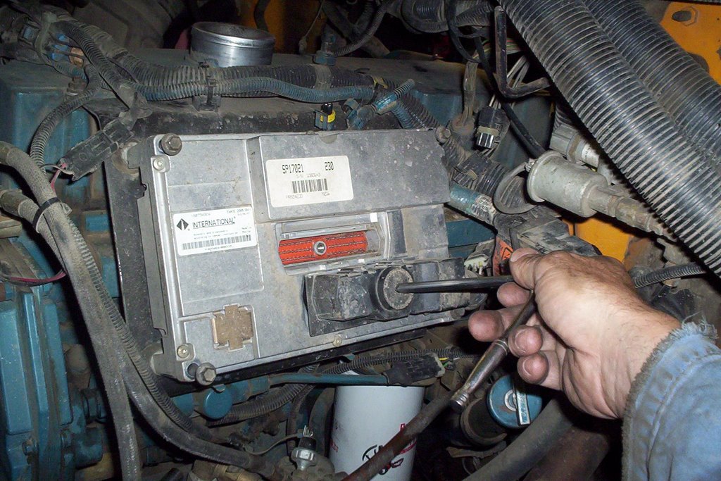
Remove the multi-pin connectors at the ECU [electronic control unit] with a 1/4 inch drive ratchet. Remove the round connector going into the valve cover housing.


Remove the 4 bolts holding ECU to the support bracket using a 10 mm socket. Remove ECU and take care it's an expensive component!
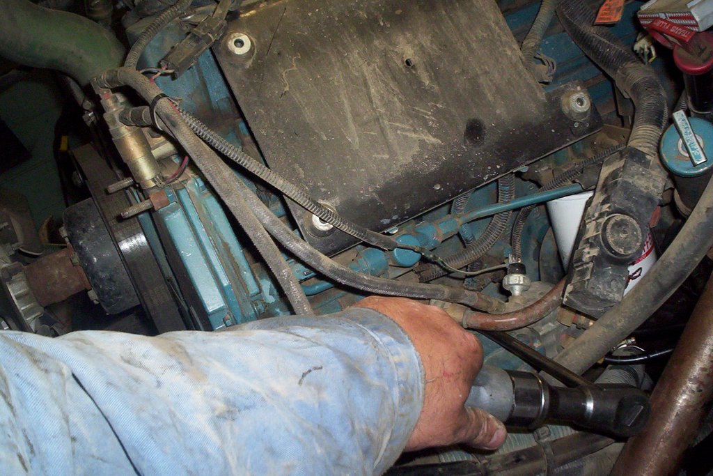

Remove ECU support bracket, there is a larger fastener below bolted to the block and 4 valve cover studs at the top side where you have to remove four retaining nuts.


Push the ECU harness connector into the valve cover housing as it will stay with the injector wiring when removing cover.
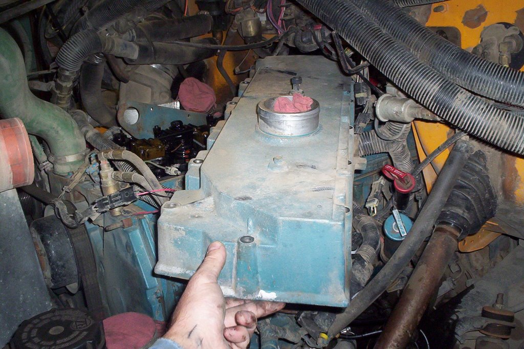

Remove valve cover, the weight has increased drastically compared to the original non-electronic engines because of the integrated intake manifold that is now part of the valve cover.

Rotate engine until TDC [top dead center] is achieved. There is a notch on the serpentine belt pulley behind the vibration dampner. An arrow and the letters TDC has been cast right into the front cover. Once lined up, the engine valves will be on #1 TDC compression or exhaust stroke.

An easy way to tell is if #1 cylinder valves are both loose and #6 cylinder valves have no clearance, then you know you are on #1 compression stroke. Note: There are 12 valves in total #1 valve being at the front while #12 valve is the last valve at the rear of of the cylinder head.

So if I say adjust #4 valve you just count from the front of the head, the first valve being #1. This makes it easier to explain which valves to adjust.

On #1 TDC compression stroke adjust adjust valves #1 #2 #3 #6 #7 #10 . The valve clearance for both intake and exhaust is .025 in. preferably with the engine cold but that's not overly crucial.

Rotate engine 360 degrees the engine is now on #6 TDC compression stroke. Adjust #4 #5 #8 #9 #11 #12 valves.

Once you have all the valves adjusted you reverse the disassembly procedure and torque the valve cover bolts to 13 ft. lbs. and the 1/4 drive wiring harness connectors at the ECU to 35 in. lbs. The valve cover gasket is reusable but still inspect it for damage or indications of wear.

I hope this helps you out when it's time to adjust valves on your DT 466E Diesel Engine.


Diesel Mechanic


Tuesday, November 16, 2010

Allison Transmission Codes & How To Retrieve Them

If you have ever wondered about Allison transmission codes and what they mean or how to retrieve them....look no further. Read the explanation below and leave a comment here on this post and I will reply with the code details. This is the first procedure a Mechanic carries out when there is a transmission complaint.

How To Retrieve an Allison Transmission Code

With the key on run... press the 2 arrows on your shift pad. You will get a D1 then 4 digits after that. The 4 digit number is the code you're after. To check for more codes press "mode" and D2 will show up with the second code (4 digits). Press Mode again D3 will come up with the fourth code and so on.

For Example: A Speed Sensor code is 2214 2212 or 2223. There are various checks you can perform. If you have a code let me know and I will post detailed transmission code troubleshooting information to help you out.

Allison transmissions come in different series, the 1000, 2000 and 3000 series depending on the size of your vehicle. The electronics is labeled as WTEC 1, 2, 3 and now 4. These are generations of the electronic systems built through the years. WTEC 3 is very common for older trucks, the tell tale sign of this type of system is the 3 plug-ins at the Transmission ECU.

This is a quick overview of Allison Transmission Codes and will be followed with a video demonstration on how to retrieve codes. Newer WTEC 4 systems require software called Allison Doc using a laptop. The video will be focusing on a WTEC 3 system using the shift pad to get codes. If you're a Mechanic, owner operator or truck enthusiast this procedure is the first step to take if you run into problems.

Check out all my Allison Automatic Transmission posts HERE  Full of Troubleshooting and Repair advice. Many faults can be repaired by running a new coaxial wire from the sensor to the ECU. If there is any interference or resistance issues with a signal to the ECU you will end up with a code.

UPDATE - VIDEOS  DEMONSTRATING HOW TO RETRIEVE AND CLEAR ALLISON TRANSMISSION CODES USING THE SHIFT PAD.

Here are 3 quick videos I made on how to use the trans shift pad to find codes. I set up a code by disconnecting the output speed sensor at the transmission. This will demonstrate what happens when a fault code occurs and what you can do to find out which code it is and how to clear it.

Video 1 - I'm purposely setting a fault code by unplugging the output speed sensor at the transmission.


Video 2 - Retrieving the transmission fault code using the shift pad.


Video 3 - Hooking the speed sensor back up to simulate the repair being completed and clearing the code using the shift pad.


As you can see Allison transmission codes are easy to read and clear using the shift pad. At the very least you can find out what the fault is and relay that information to your mechanic or use it to troubleshoot the problem yourself. I had a service call once in the middle of the winter, the bus was stuck in 1st gear.

Sound familiar? What had happened was the connector and harness accumulated so much ice around it the weight actually pulled the connector out of the output speed sensor socket. That was weird but made for a happy ending. Another common code is '3500' which is the battery voltage feed to the ECU, battery voltage is hard wired to the ECU so if their is any interruption you're going to get that code number.

Please post your comments and questions below and I will get back to you. thanks!

CLICK HERE FOR THE ALLISON SHIFT SELECTOR OPERATION AND CODE MANUAL.
NOTE: This is for a 2009 4th generation Allison Transmission.

Sunday, May 16, 2010

Mechanic Education Includes On The Job Training


For the last month we had a student from Thompson Rivers University (just across the street from our location) complete a one month Practicum in our shop. His name was Dustin & he came in personally to ask if we would give him the chance to hang out with us to complete his course.


I immediately agreed to accept him into our workplace since it's nice to have the chance to mentor someone just starting out in this trade.

I have a personal connection to TRU since I started in the pre-app course there when it was called Cariboo College.

Dustin's course was called "Heavy Duty Mechanic & Commercial Transport Vehicle Mechanic Foundation Program" a 36 week course.

He emphasized his desire to get into Commercial Transport so I got him into the mix fast giving him hands-on experience with fabricating, brake jobs, electrical, automotive, servicing, vehicle inspections, trailers, hooking up / finding engine codes and he even experienced a service call.

I added up the experience in years of all the Mechanics working in our garage and it was approximately 135 years. This was a huge advantage for Dustin to learn and ask questions. The practicum is a great idea for anyone wanting to get into a trade and see what it's like to perform real work on equipment that operates on our streets and highways.

It was a pleasure to share experience and knowledge with someone like Dustin who was clearly interested in the Commercial Transport Mechanic trade.

Wednesday, March 25, 2009

Cummins Diesel Engine Drive Gears

If you were to remove the front cover off of any diesel engine you will come across a series of drive gears. No belts or chains here, you're looking at the timing gears that make this diesel engine run. Each gear is timed to each other with specially placed marks that must be lined up during assembly.

Enlarge this picture by clicking on it and you should see the timing marks on the crank and cam gears. They look like center punch marks one on the crank and two marks on the camshaft.

The crankshaft and camshaft gears are driven together to provide proper valve and piston timing for combustion to occur. Fuel injection timing on the Cummins C Model diesel engine (pictured here) is accomplished by inserting a pin into the injection pump drive gear (top right).

The pump in turn has a pin in the side of it's housing that has to be removed, flipped around & aligned into the injection pump shaft setting it for injection on #1 cylinder.

The oil pump is also driven off of the crank gear and idler gear. The air compressor is located lower right without it's drive gear installed.