Looking at DC Generators Fundamentals you can easily relate to Hybrid Automobiles which are powered by a fuel driven engine to create DC current that charges the batteries that drive the electric motors that drive the wheels.
Diesel locomotives are, for example, an example of a hybrid drive train, as the diesel engine does not cause the wheels to spin, but instead generates electricity that turns electric motors that then cause the wheels to spin.
There are two kinds of hybrid drive trains:
* Serial hybrid: The thing which turns the wheel is an electric motor, and the gasoline engine is used purely to generate electricity.
* Parallel hybrid: Both the electric motor and gasoline engine can cause the wheels to turn.
These "new" hybrid cars are all of the parallel design pattern. Not a one, so far, is of the serial design pattern even though that would be a much simpler vehicle to design and build. A simple-and-obvious-to-construct serial hybrid vehicle would be an otherwise pure electric car, and carry a portable generator.
When the batteries run low, fire up the portable generator and make some electricity. You could recharge the battery pack from the power grid, or from the generator, your choice. This could turn a limited range electric vehicle into one that could drive long distances.
However there are several steps of converting power (e.g. mechanical to electrical, and AC to DC). Each conversion step involves some lossage, and maybe this isn't the most efficient use of fuel.
The automakers are also working with a third type of hybrid, that they call "mild hybrid". [No information available yet]
It's not electric unless you can plug it in.
That is, many people seem to think the hybrid-electric vehicles on the market now are electric. Well, honestly, are they? None of them let you plug the car in to charge the batteries, none of them drive for any significant distance on pure electric, so how can one honestly think of them as an electric vehicle?
The electricity used in the electric motor, in all of these vehicles, comes from gasoline burned in the gas or diesel engine. These are not electric vehicles, despite the presence of that electric motor.
One day there will be 100% electric vehicles but technology will have to come up with a super/cost effective deep cell battery that will absorb and retain an amazing amount of amperage.
Here is a Youtube Video on a very old DC Generator that was steam engine driven back in 1917. It's a great example on how a driven DC Generator can be used to charge the battery pack [i.e. hybrid vehicle] or supply an amperage to a load. In this video the load is obviously the light being held for the demo...
DC Generators Fundamentals
Showing posts with label test. Show all posts
Showing posts with label test. Show all posts
Tuesday, January 01, 2008


Wednesday, December 19, 2007
Charging System Test - Heavy Duty 12 Volt System
 A charging system test is a very basic operation with the right tools. Pictured is a Leece Neville 160 Amp Alternator which works very hard to keep the three 900 CCA [Cold Cranking Amps] bus batteries charged. Thomas School buses have a large demand with extra lights, electric motors and the engine air intake heater. The diesel engine in this case is a Cummins ISC Electronically controlled unit.
 You're probably wondering what the heck is that device hooked up to the batteries? That's my tool of choice, a 'SUN' VAT 33 [Volt Amp Tester]. This model has been around for decades and still very reliable, our shop does have a digital tester but I like this one for doing a quick check on the charging system. The reason I'm testing the charging system is because of an unusually low voltmeter & ammeter reading.

The main leads are hooked up to the positive and negative battery terminals while the amps pickup is clamped around the positive cable to read alternator ouput back into the batteries. The engine must be running at high idle [approx. 1200 rpm]
The black control knob I'm turning puts a load on the batteries which should kick in the alternator to charge very close to maximum. Once I bring down the system voltage to 12V the alternator should normally put out a full charge of approx. 160 amps.
The test revealed the alternator is only putting out 80 amps maximum which will not keep up to the demands of a fully operational school bus & must be repaired or replaced.
This is a fast and easy way to do a charging system test on a 12 Volt Heavy Duty charging system.
Click here to sell your car online at eBay!

Sunday, October 14, 2007
Allison Automatic Transmission Wiring & Troubleshooting
 The Allison Transmission Control Unit on the 1999 Saf-T-Liner is located under the floor directly below the driver. There are 3 plug-ins which is an easy way to tell this is a W-TEC 3 system [World Transmission Electronic Unit 3rd generation]. The Transmission vehicle speed signal enters here and exits at two different plugs, one for the speedometer and the other to the Cummins ISC ECU.
 We will trace the exiting wire from the ECU that provides our Vehicle Speed Signal since that is the code and the speedometer is operating normally. Since we have speedo operation that gives us an obvious clue that the incoming signal to the Trans ECU is OK.[resistance should be checked regardless]
The wire we want to trace goes from the Trans ECU to the VIM [Vehicle Interface Module]
Removing the dash back cover makes this check MUCH easier.
 Remove the cover from the VIM
 The VIM is an interface between the Trans ECU and the chasis wiring. Various operations are accomplished through this module like the exhaust brake, back up lights, neutral start, high idle and of course our vehicle speed signal runs through here to the Engine ECU.
[Click the Pic to Enlarge]
Now we can check the continuity and see if we have a circuit. After checking this out there is no connection between the Trans. ECU and the VIM.
I'll run a new wire to repair the open circuit, an easy fix. It's nice to get a gimme once in awhile!
In the VIM you'll notice a series of relays and 2 fuses. If you experience a dead keypad and there is battery voltage to the VIM then check these fuses. One is main power & the other is ignition power.

The other vehicle speed signal wire [tan wire # 157] comes from the trans ECU directly to the speedo. The speed signal to the VIM is the same number [tan wire #157] since it comes from a different plug.
 This is where it all begins from the output shaft housing of the transmission. The output sensor is a single coil unit that sends an AC voltage to the Trans ECU.
There is a toothed wheel rotating inside the housing that creates the signal to the sensor.
The Allison 3000 Automatic Transmission is a very reliable unit when maintained properly. The wiring problems come and go but are easy to trace and repair with the right tools and wiring diagrams.
Thursday, October 04, 2007
Testing A Starter Solenoid
Check out this excellent video on Electromagnetism. This is the principle that solenoids and relays use to provide the most efficient electrical circuits. It's over 10 minutes long so grab your favorite beverage and have a look.
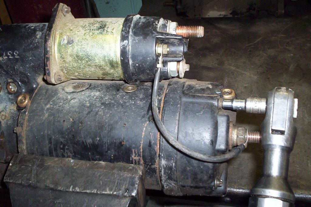
The principles here will give you a much better idea how components work like a starter solenoid. Following this video is my own on bench testing a starter solenoid which connects the Battery to the starter motor and engages the starter drive with the engine flywheel.
Below is a demonstration on bench testing a starter by simply connecting battery supply to the solenoid positive terminal and the ground terminal at the starter motor.
The switch terminal which is marked "S" is the signal from the ignition switch that energizes the coil in the solenoid and turns it into an electromagnet forcing the contact plate to connect the main battery power to the motor.
Here is an older post on the disassembly & repair of a Delco 37 MT Starter

The principles here will give you a much better idea how components work like a starter solenoid. Following this video is my own on bench testing a starter solenoid which connects the Battery to the starter motor and engages the starter drive with the engine flywheel.
Below is a demonstration on bench testing a starter by simply connecting battery supply to the solenoid positive terminal and the ground terminal at the starter motor.
The switch terminal which is marked "S" is the signal from the ignition switch that energizes the coil in the solenoid and turns it into an electromagnet forcing the contact plate to connect the main battery power to the motor.
Here is an older post on the disassembly & repair of a Delco 37 MT Starter
Subscribe to:
Posts
(
Atom
)