Working on a fleet of buses has some amusing moments. Especially when 12 Volt systems and moisture come into play. Mechanics go to school to get the basics, then you need to use those basics and go much deeper. Experience indeed is the best teacher and mechanic information on symptoms and troubleshooting can be shared and recorded for the benefit of the entire shop and right here on this blog for future use.
Below is what I call a 'Mechanic's Special'
The driver complaint is the back up alarm and reverse lights come on all the time even in neutral. So the first thing to think about is what could possibly cause this to happen without touching the controls. With the key on we have full operation of the back up warning system. The HDX Thomas pusher we are working on has the VIM (vehicle interface module) mounted above the steering axle (Lots of snow and ice). This is the first place to check since the interface module receives the reverse signal from the Trans ECU after the driver selects reverse. CLICK ON PICTURE TO ENLARGE.
The VIM has relays and fuses (BELOW) to control the circuits on the chassis side of the bus including the high idle, neutral start and reverse warning. Luckily once we pulled off the lid to the VIM we heard a buzzing noise. This is not normal and is a mechanic troubleshooting red flag, you want to look for abnormal mechanical situations.
After opening the VIM up the problem was obvious. The corrosion was making a circuit from battery to the reverse warning system. Moisture, oxygen and 12 Volt electrical circuits love each other and create double trouble after uniting for a given period of time.
Here is my 'KEEP IT SIMPLE' drawing (BELOW) of the circuit in question. The operator chooses reverse, the transmission shifts and the reverse signal is fed to the Vehicle Interface Module to the reverse relay and 12 Volt power feeds the reverse alarm and lights.
Once you know how a circuit works it makes the problem solving much easier and common sense will prevail. This problem can happen anywhere so be prepared. Checking electrical problem circuits and components closest to the environment pays off more times than not. I hope you got something out of this Mechanic Information.
Please leave a comment below and share any 12 volt electrical experiences you've had in the past or just let me know you got something out of this info.
A fuel guage sending unit is a ground circuit for the fuel guage. The position of the sender float changes the resistance to ground by way of a resistance winding that is built into the sending unit. High or low resistance determines a full or empty fuel tank. The complaint I'm dealing with is an erratic fuel guage reading, the guage needle is bouncing all over the place every time the driver turns or stops suddenly. This Mechanic information is for anyone who knows how to turn a wrench and you'll see how easy it is to check out the sending unit. Firstly, every fuel guage sending unit is very similar on older vehicles. On newer automotive applications the sender is built into the fuel tank electric fuel pump assy. This is an integral unit and quite expensive. I'm working on a 2000 Thomas BusSaf-T-Liner which is running a CumminsISC Diesel Engine. In this case the sender is seperate and very easy to test. The sender is located 3 seats back under the floor. The floor plate has to be removed to gain access. The sender can be tested using a jumper wire. Disconnect the wire connector at the middle terminal of the sender [this comes from the fuel guage]. Connect the jumper to the loose wire and hook it to ground. [click on each picture to enlarge] Turn on the ignition switch and the guage should go right over to the full mark. What this does is tell us the gauge is OK since the wire to the sender has been grounded directly without any resistance. The sender has been bypassed and now we're sure it has to be replaced. Remove the retaining screws and ground return wire and replace the sender the same way it came out. It's that easy! So now you understand the circuit through a fuel guage sending unit and how easy it is to diagnose and repair. I hope this mechanic information has helped you.
Thomas Bus HDX Pushers have a rear emergency exit window that has 2 ground switches. One for the alarm, warning the driver that the window is open and the other is an interlock that does not allow the bus to start when the window is latched.
The problem we were having was water seeping through the seal causing a circuit to ground tripping the alarm even when the window was fully closed. The quick fix was to grab an air line and dry off around the switch and grounds. Pictured here is the alarm ground switch[click on pic to enlarge]
This is the window locking latch that must be unlatched for the bus to start. The rivet on the outside is going to ground while the handle contacts a strip riveted on the inside of the frame.
We installed 2 intermittent switches in a currently available Thomas Part that encases the 2 switches and does the same job as the factory install.
The window must be removed to rewire the new installation. The 2 original ground switch wires are attached to the new switches in the casing and grounded at the case.
Once installed the [starting interlock] bolt style latch locks the window and the other switch is depressed [just above] to shut off the window alarm. The latch catches on a "C" shaped flat bar that was fabricated to lock the window.
The latch bolt is in the open [run] position and the bus will start, this is a safety factor that newer Thomas Buses come with from the factory.
I will be updating this post soon with part numbers.
Thomas Buses are driven by an Allison MD 3000 SeriesAutomatic transmission. This 1995 Saf-t-liner model had no power to the operators trans shift pad. The shift pad is also the Trans ECU [electronic control unit] so as I have said before always check the source , in this case the batteries.
There was a power feed open between the batteries and the rear control box at the engine compartment. I was able to limp the bus home by jumping battery power to the terminal board inside the control box which goes to directly to the operators cab supplying battery power to the shift pad/ECU.
This is obviously how I determined the open from the battery to the control box/terminal board [standard wiring on all Saf-t-liners]. The code for this fault is 35-00[push both arrows on the shift pad at the same time with key on to retrieve code {under normal circumstances}
The control box at the engine compartment houses the engine intake heater components, lights etc. as well as the main battery power to the front electrical control box below the driver's side window.
My plan is to totally bypass the trans battery supply circuit from the battery to the ECU. Here you can see I've already cut the wires [larger #8 guagepos. and neg. wiring come from the battery while the smaller #10 guagepos. and neg. wires are running up front to the ECU]
This is the terminal board I mentioned earlier, factory wiring with spade connectors that connect the battery feed wiring to the trans. ECU wiring.
The first picture [top] shows the #8 pos. and neg. wires hooked up and running directly to the trans ECU. This will eliminate the extra #10 wires shown in the rear control box.
In the drivers cab the rear cover has been removed for easy access to the back of the trans. ECU. The upper plug can be removed and inspected for battery power. Both pos. and neg. #18 wires [2 each] run into this plug directly from the battery. The #8 wire is downsized under the dash to accommodate the smaller wiring into the ECU plug-in.
The 12V source from the battery is shown here with no connections in between. With a Digital Multimeter you can check for a battery voltage and a good ground.
So now you know when you have a shift pad with no reading [key on] the first thing to check is the battery voltage.
I hope this has helped you become more familiar with Thomas Buses equipped with Allison MD 3000 Series Automatic Transmissions.
Thomas Buses have a signal switch that is very easy to replace. Most of the time the switch does not cancel properly which is a pain for drivers who have other things to look after and don't want to be constantly reaching for the the signal switch to manually turn it off after every corner. The Thomas School Bus Saf-t-linersare similar with many similar components, the signal switch design did not change for many years.
Remove the upper and lower covers on the steering column. The upper cover is easier to remove when the steering column is tilted all the way down.
Use an allen wrench to remove the 2 signal switch screws holding it to the column.
Here is a top view of the upper screw being removed. As you can see the access to the signal switch is very easy.
Unplug the 2 wiring harnesses to the signal switch, they only fit one way.
Important Note:
One thing that you should watch for is to make sure the wiring running down the steering coluumn has enough slack. I've had problems where the signals do not work or short out on the column because of not having enough extra wiring to accommodate the tilt steering column movement .
The signal arm is held in the switch with a catch and can be removed by pulling on it aggressively until it releases from the switch.
Reverse this procedure and now you know how to replace the signal switch on Thomas Buses.
Cummins Engine Repair not only involves mechanical but electronic repairs as well. The ISC model has an ECM that sends and receives messages that controls every performance aspect of this engine. The main source of power is the battery that depends on wiring that feeds the Cummins ECM sufficient voltage to run the engine systems. Pictured is the laptop shot of an active code #434 a power interruption that derated the engine to a crawl. Derating protects the engine from sustaining high speeds and rpms which would cause more severe damage. This ISC Cummins Engine is in a 1999 Thomas School Bus Saf-T-Liner.With an active code you can retrieve it with the diagnostics switch [on the dash] & ignition switch turned on. The code will beep each number with a pause, in this case 4 beeps 3 beeps 4 beeps with a pause in between each #.
A closer look [click on photo to enlarge] shows numerous fuses on the positive feed wire to the Engine ECM [electronic control module]. Our code information is telling me there is a power problem so "the first thing to check is the Source."
Using a digital ohmmeter check the fuses for continuity and clean all the connections.
Note: Before this maintenance step I could not get a reading on my laptop, there was a communication error between the engine and the "Cummins Insite" software. After cleaning all the connections and testing the batteries the communication problem was erased and the code disappeared.
There is a variety of 7.5 and 10 amp fuses inline with battery to ECU supply power. I traced the wiring back along the frame as well to check out any other possible problems. The rule of thumb in this situation is to check connections and wiring closest to the environment and work your way up the line.
Using a Snap-On Micro Vat Battery Tester I concluded that all the batteries were in good condition. This tester does a very quick assessment of battery condition and also tests starting and charging systems quickly.
The Conclusion to this problem was simple, servicing the battery connections which had enough resistance to cause the #434 code to occur. It makes sense since the ECM reads Voltage at a very sensitive level.
After an extensive road test the code did not come back and this experience was a good one telling me [and you the reader] to always check the simple things first!
Thomas Buses have changed through the years and one model with a different electrical layout is the HDX. This 2004 has everything in a totally different layout compared to the Saf-T-Liner.
The Body Electrical [lights and accessories] Schematic is nicely displayed on the side door panel below the driver's side window.
[Click On Each Photo To Enlarge]
The circuit board shown here has been unfastened and tipped downward so you can see the many connectors that hook up with relays and battery supply junctions. There are 3 circuit boards in total with specific spots for each connector.
The circuit board is upright once again [located in the side panel] Here you can see the main battery power supply on the left with the many fuses and relays required to run lights, heater motors, solenoids etc. The LED lights above indicate which relays are active, YELLOW indicates the relay coil has been activated while the GREEN LED indicates the circuit is connected to the load.
Thomas Buses have evolved from the basic "battery to load with a switch in between" to complex relays & mult-functional switches that handle the demand for more circuits that can meet the load & safety component demands of today's School Buses.
Looking at DC Generators Fundamentals you can easily relate to Hybrid Automobiles which are powered by a fuel driven engine to create DC current that charges the batteries that drive the electric motors that drive the wheels.
Diesel locomotives are, for example, an example of a hybrid drive train, as the diesel engine does not cause the wheels to spin, but instead generates electricity that turns electric motors that then cause the wheels to spin.
There are two kinds of hybrid drive trains:
* Serial hybrid: The thing which turns the wheel is an electric motor, and the gasoline engine is used purely to generate electricity.
* Parallel hybrid: Both the electric motor and gasoline engine can cause the wheels to turn.
These "new" hybrid cars are all of the parallel design pattern. Not a one, so far, is of the serial design pattern even though that would be a much simpler vehicle to design and build. A simple-and-obvious-to-construct serial hybrid vehicle would be an otherwise pure electric car, and carry a portable generator.
When the batteries run low, fire up the portable generator and make some electricity. You could recharge the battery pack from the power grid, or from the generator, your choice. This could turn a limited range electric vehicle into one that could drive long distances.
However there are several steps of converting power (e.g. mechanical to electrical, and AC to DC). Each conversion step involves some lossage, and maybe this isn't the most efficient use of fuel.
The automakers are also working with a third type of hybrid, that they call "mild hybrid". [No information available yet]
It's not electric unless you can plug it in.
That is, many people seem to think the hybrid-electric vehicles on the market now are electric. Well, honestly, are they? None of them let you plug the car in to charge the batteries, none of them drive for any significant distance on pure electric, so how can one honestly think of them as an electric vehicle?
The electricity used in the electric motor, in all of these vehicles, comes from gasoline burned in the gas or diesel engine. These are not electric vehicles, despite the presence of that electric motor.
One day there will be 100% electric vehicles but technology will have to come up with a super/cost effective deep cell battery that will absorb and retain an amazing amount of amperage.
Here is a Youtube Video on a very old DC Generator that was steam engine driven back in 1917. It's a great example on how a driven DC Generator can be used to charge the battery pack [i.e. hybrid vehicle] or supply an amperage to a load. In this video the load is obviously the light being held for the demo...
A charging system test is a very basic operation with the right tools. Pictured is a Leece Neville 160 Amp Alternator which works very hard to keep the three 900 CCA [Cold Cranking Amps] bus batteries charged. Thomas School buses have a large demand with extra lights, electric motors and the engine air intake heater. The diesel engine in this case is a Cummins ISC Electronically controlled unit.
You're probably wondering what the heck is that device hooked up to the batteries? That's my tool of choice, a 'SUN' VAT 33 [Volt Amp Tester]. This model has been around for decades and still very reliable, our shop does have a digital tester but I like this one for doing a quick check on the charging system. The reason I'm testing the charging system is because of an unusually low voltmeter & ammeter reading.
The main leads are hooked up to the positive and negative battery terminals while the amps pickup is clamped around the positive cable to read alternator ouput back into the batteries. The engine must be running at high idle [approx. 1200 rpm]
The black control knob I'm turning puts a load on the batteries which should kick in the alternator to charge very close to maximum. Once I bring down the system voltage to 12V the alternator should normally put out a full charge of approx. 160 amps.
The test revealed the alternator is only putting out 80 amps maximum which will not keep up to the demands of a fully operational school bus & must be repaired or replaced.
This is a fast and easy way to do a charging system test on a 12 Volt Heavy Duty charging system.
The electrical system on Thomas Buses vary depending on the model, pictured is an HDX model built in 2004. We are going to change a module that controls the main power to the body and chassis electrical systems. A hoist is handy but not totally required, I had to enlist a grinder with a cut-off wheel to remove the existing bolts.
This unit is called a dual power switch that is mounted on the frame on the passenger side across from the transmission. Since it is exposed to the elements the terminals are exposed so corrosion can develop. Consequently their is a possibility of an intermittent power problem to the lights or engine/trans controls when turning on the ignition.
As you can see the middle terminal is connected directly to the main batteries. The chassis and body battery supply terminals are located on each side while the ignition feed connector is plugged in on the top left corner. When the ignition is energized a signal is sent to this module and power is directed to both systems. The chassis is the engine, trans. and running electrical while the body electrical is the lighting system.
Here is the module installed on the frame with four fasteners and an insulator between the module and the frame surface. It depends totally on what kind of environment you drive in for a problem to occur with this component. It is very well sealed internally with a hard epoxy type substance. I hope this article has enlightened you with what to look for when experiencing electrical problems with Thomas Buses.
There are 4 Front heater blower motors on the Thomas School Bus Saf-T-Liner Model. With Winter on it's way this is an important maintenance area, defrosting of the windshield has to be accomplished quickly. The heater blower motors also serve as defrost motors with a quick change up on the controls. Each motor has 4 wires for high/low speed and 2 grounds. The direction can be reversed using the ground wires. One is grounded directly while the other is connected internally back to the motor, reversing these 2 will change direction.
This Thomas Pusher Bus is a 1992 model, removing the middle and left side panels will allow access to all 4 heater blower motors. The tandem motor in the middle looks after main defrost and heat while each motor on the ends provide floor heat to the driver and defrost/heat to both ends of the cab. The main failures on these motors are dry bushings causing noise and seizure and blower cage noise.
Check out this excellent video on Electromagnetism. This is the principle that solenoids and relays use to provide the most efficient electrical circuits. It's over 10 minutes long so grab your favorite beverage and have a look.
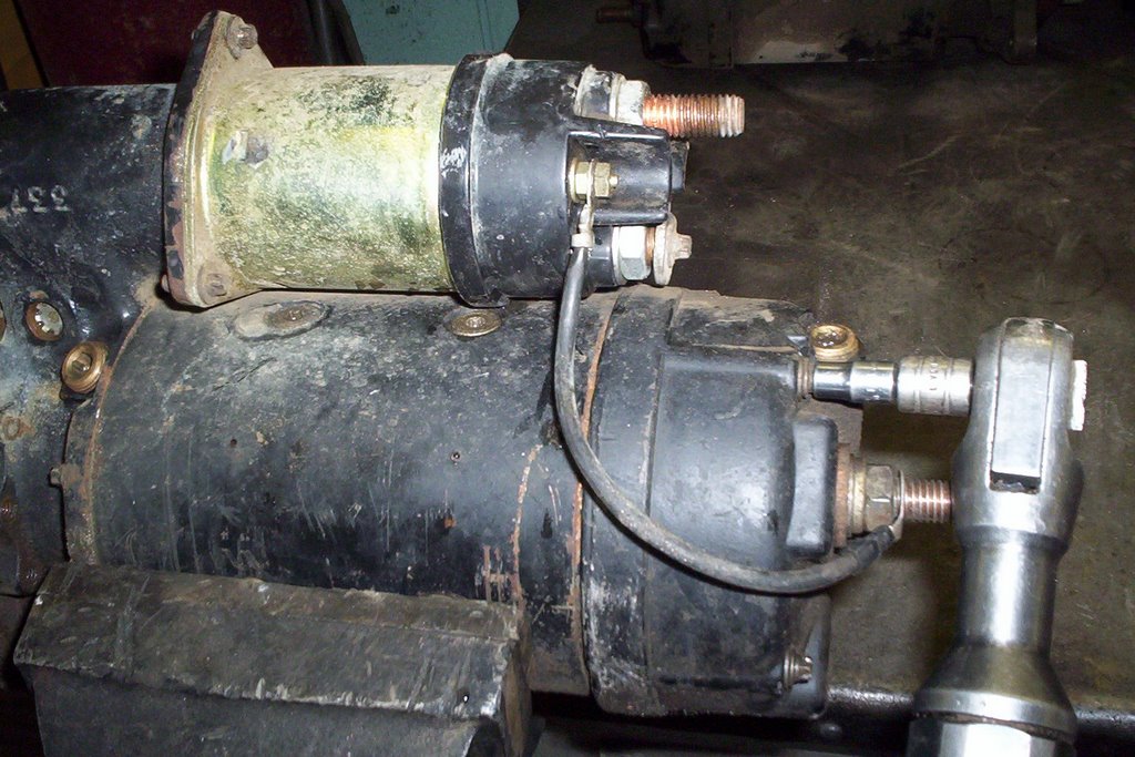
The principles here will give you a much better idea how components work like a starter solenoid. Following this video is my own on bench testing a starter solenoid which connects the Battery to the starter motor and engages the starter drive with the engine flywheel.
Below is a demonstration on bench testing a starter by simply connecting battery supply to the solenoid positive terminal and the ground terminal at the starter motor.
The switch terminal which is marked "S" is the signal from the ignition switch that energizes the coil in the solenoid and turns it into an electromagnet forcing the contact plate to connect the main battery power to the motor.
Basic Electricity applies to any type of machinery running on a 12 Volt Direct Current system. Once you see how it works it's much easier to understand, instead of making it complicated I will explain the basics in layman's terms. This is the chasis electrical panel on a 1995 Thomas Saf-T-Liner[pusher]. note: Click on the Photos to Enlarge It looks a lot more complicated than it really is. Any 12 Volt electrical system has a source of power from the batteries, in this case we run on 3 top post 900 CCA [cold cranking amp rated] batteries.
That's a lot of juice available to supply voltage to the body and chasis circuits, but there are environmental and mechanical factors that will cause a severe voltage drop if not detected.
Voltage is like a river, the heavier the flow the stronger the current. If there's a dam down river this will cause resistance and restrict the flow. If the source [the river] is cut off so is the flow.
Any resistance between the battery and the load will cause a voltage drop, this can be caused by a short circuit, open circuit or just plain resistance from corrosion. A good rule of thumb when troubleshooting a 12 volt circuit is to:
Step 1...Check the battery -Sufficient Voltage? Step 2...Check the load i.e. A Light or Relay, is it working? Step 3...Check the connections Step 4...Check the wiring
Very basic steps but most electrical problems are found using these steps, check the simple things first.
Say for instance you have 13.5 volts at the battery and 0.0 volts at the load. This means you have an obvious Open Circuit problem [a rubbed through wire possibly]
Using a digital ohmmeter you can ground one end of the circuit and using the two ohmmeter leads at the other end connect one lead to the faulty wire and the other end to ground. What you're doing here is checking for Continuity [the ohmmeter has it's own battery voltage which runs through the faulty wire].
By the way, the multi-meter you use for newer equipment must be Digital to safeguard the electronic systems that are much more common in new trucks and buses. If the circuit breaker is popping on and off then there is obviously a Short Circuitwhich can be hunted down using a Short Finder [a very slick tool to have which saves a lot of time and grief]
You hook up the auto-reset breaker then slide the meter along the wiring until it finds the exact spot where the short is [the indicator needle stops moving] along the frame or body. Clean the connections and check the load i.e. marker light or tail light for poor grounds & connections. That's a Quick Overview on Troubleshooting a Basic 12 Volt Electrical Circuit.


 A charging system test is a very basic operation with the right tools. Pictured is a Leece Neville 160 Amp Alternator which works very hard to keep the three 900 CCA [Cold Cranking Amps] bus batteries charged. Thomas School buses have a large demand with extra lights, electric motors and the engine air intake heater. The diesel engine in this case is a Cummins ISC Electronically controlled unit.


 This Thomas Pusher Bus is a 1992 model, removing the middle and left side panels will allow access to all 4 heater blower motors.