Here's a video I put together going through the steps to rebuilding and installing a Cat 3116 Diesel engine in a pusher school bus. It's a big job and you can see it happen in a matter of minutes. It's much easier to assemble the transmission to the engine and use the trans jack for support and hydraulic hoist on the front end.
The whole works rolls right into the frame. Thankfully Thomas Bus allows the rear end frame to be removed. The Cat 3116 is a fussy engine to set up and you MUST have the Cat tool kit. There is no way to set up the timing, synchronization & fuel setting without the kit.
The valve train is the only weak spot on these engines, when they get too hot (in this case) the exhaust valve let loose requiring the major repair including a new cylinder head. Too avoid this keep the engine temperature down and check valve adjustment every 30,000 to 40,000 km (18-24,000 Miles). Enjoy the video....Please Leave a Comment
School Bus Mechanic Pictures..Exclusive! by jelletse
Showing posts with label cat 3116. Show all posts
Showing posts with label cat 3116. Show all posts
Wednesday, April 06, 2011


Wednesday, December 22, 2010
How To Set Valves & Injectors - Cat 3116 Diesel Engine
Diesel Mechanic Tips:
Today I am going to show you how to adjust the valves and injectors on a Caterpillar 3116 Diesel Engine. The injectors are mechanical and are checked and adjusted manually using the appropriate Caterpillar tune-up tools.
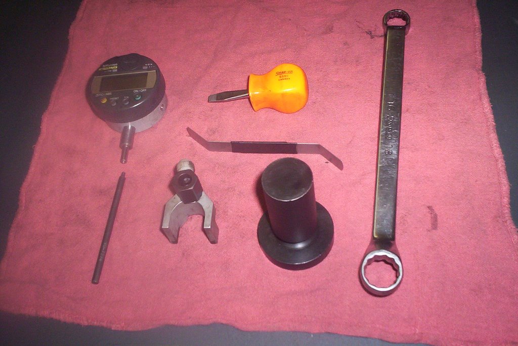
Here are the tools needed to perform the valve and injector adjustment:
Caterpillar Part #'s
*Dial Indicator # 1U-8869
*Contact Point # 9U-7274
*Feeler Guage # 123-4941
*16mm/18mm Drop Wrench # 128-8824
* Timing Guage Block # 9U-7269
Magnetic Base # 123-4940
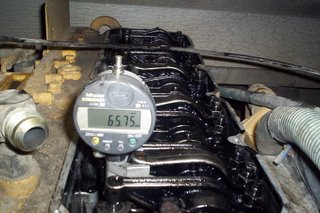
 The dial indicator has to be pre-set so it reads 62.00 mm when placed on the timing guage block as shown below. These tools come with the complete Caterpillar tune-up kit with detailed instructions included.

 The first thing to do is rotate the engine over until # 6 cylinder valve rockers are rocking. Watch # 6 valve rockers as you are rotating the engine, keep turning the engine until the exhaust valve closes and the intake valve JUST starts to open. Stop there, # 1 cylinder is now on the Compression Stroke and ready for valve adjustment as well as the other designated injectors and valves.
Today I am going to show you how to adjust the valves and injectors on a Caterpillar 3116 Diesel Engine. The injectors are mechanical and are checked and adjusted manually using the appropriate Caterpillar tune-up tools.
Here are the tools needed to perform the valve and injector adjustment:
Caterpillar Part #'s
*Dial Indicator # 1U-8869
*Contact Point # 9U-7274
*Feeler Guage # 123-4941
*16mm/18mm Drop Wrench # 128-8824
* Timing Guage Block # 9U-7269
Magnetic Base # 123-4940
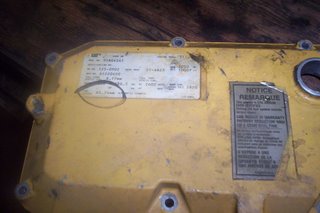
 Setting the valves and injectors is a preventive maintenance operation and should be done on a regular basis. Once you get through one setting it's a cakewalk the second time around. Below is the dataplate that tells you the timing specification for setting injectors.
 The dial indicator has to be pre-set so it reads 62.00 mm when placed on the timing guage block as shown below. These tools come with the complete Caterpillar tune-up kit with detailed instructions included.
 The first thing to do is rotate the engine over until # 6 cylinder valve rockers are rocking. Watch # 6 valve rockers as you are rotating the engine, keep turning the engine until the exhaust valve closes and the intake valve JUST starts to open. Stop there, # 1 cylinder is now on the Compression Stroke and ready for valve adjustment as well as the other designated injectors and valves.
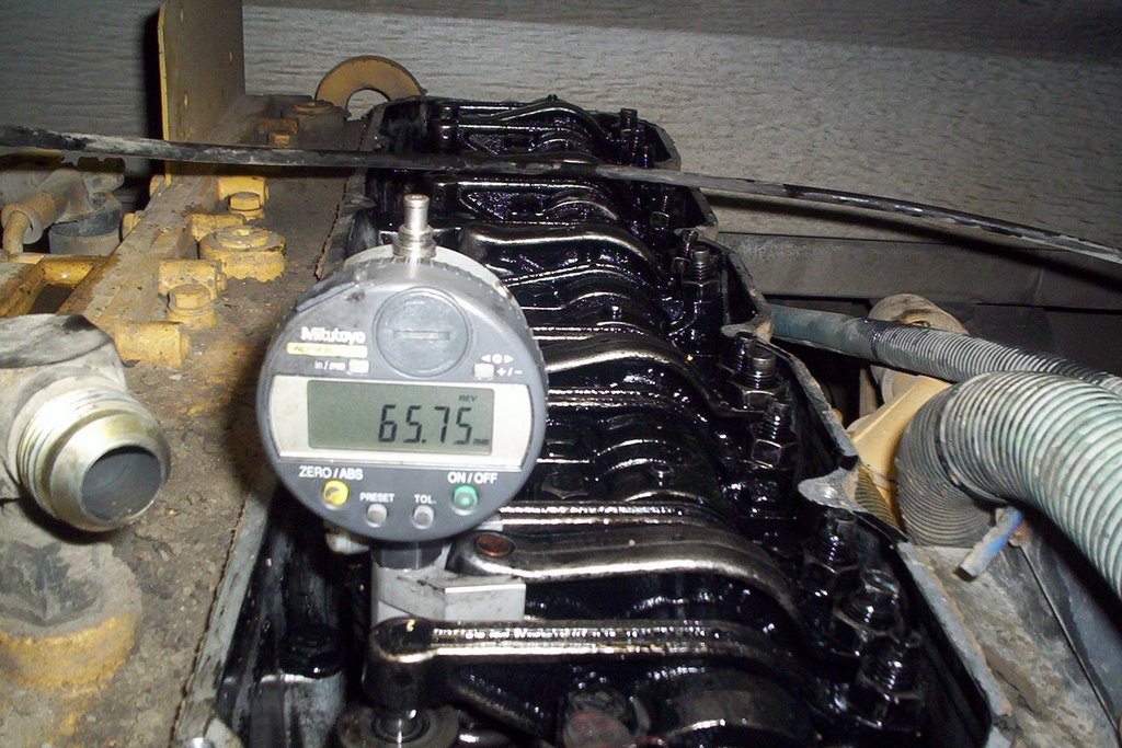
 *Adjust 3-5-6 injectors to timing spec. / in this case 65.74 mm / + or - .020 mm
*Adjust 1-2-4 intake valves .015 in.
*Adjust 1-3-5 exhaust valves .025 in.
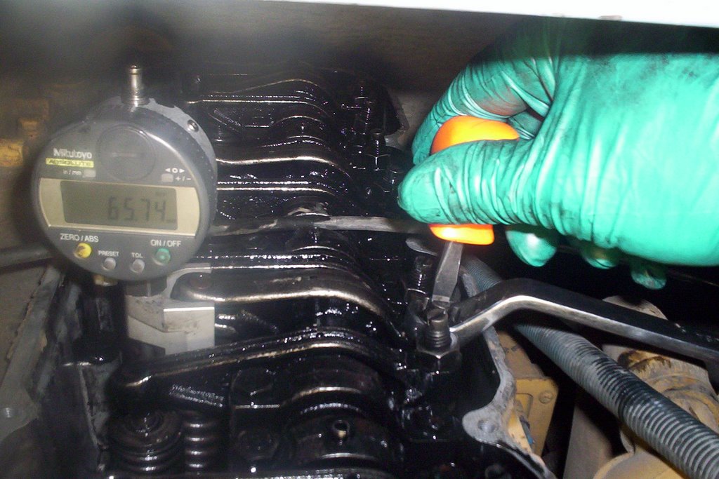 Rotate engine over 360 degrees and adjust the other remaining valves and injectors. # 6 cylinder is now on compression stroke since #1 and # 6 pistons are always at TDC [top dead center]together.
*Adjust 1-2-4 injectors
*Adjust 3-5-6 intake valves
*Adjust 2-4-6 exhaust valves
As you can see from the above picture the magnetic dial indicator holder sits on top of the injector. The dial indicator measures the distance from the top of the injector to the machined body surface at the bottom which must be set correctly. This dimension effects injection timing and can be adjusted at the injector rocker arm set screw.
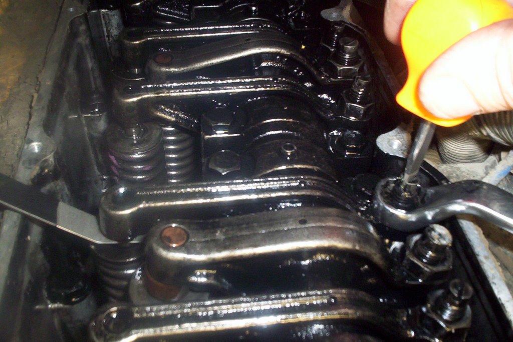
I hope this post helps out all you Cat 3116 owners. The valve and injector adjustment is probably the most crucial as adjustment can change with normal wear and tear as your diesel engine racks up the mileage.
That's all for now, thanks for visiting and be sure to check back for more Diesel Mechanic Tips.
Thursday, July 09, 2009
Cat 3116 Troubleshooting No Power
The problem with this 3116 Cat Diesel Engine was no power. The funny thing was it felt like someone stuck a banana in the tailpipe. There was no engine miss or hesitation what so ever. I checked for excessive back-pressure and that was normal.
One thing that seemed curious was the rpms in neutral went to the maximum without any problem but as soon as you put a load on the engine the rpms stayed at around 1200 rpm with no torque at all.
 Here is a picture of the old diaphragm with a split in it. I remember the red flag that popped into my head when I called the Cat dealer for this part and they had 3 diaphragms on the shelf. Perhaps a recurring problem?
 The 3 allen head screws are removed to pull the cover off to replace the diaphragm. This is an easy procedure once the governor is removed from the engine.
 The governor linkage must be unhooked from the fuel rack before removing. Here you can see the pin which slides into the linkage and secured with a C clip.
 The governor does not have to be timed and is fastened to the engine with 3 m8 bolts. Not much to it once all the fuel lines and piping is removed. This was a case of a smooth No Power situation. There was no white or black smoke, the engine did not miss or do anything really obvious. Testing the diaphragm with the air regulator is just another way for a diesel mechanic to troubleshoot a Cat 3116 Diesel Engine.
One thing that seemed curious was the rpms in neutral went to the maximum without any problem but as soon as you put a load on the engine the rpms stayed at around 1200 rpm with no torque at all.
 The Cat 3116 Governor controls the fuel rack which in turn decides how much fuel to allow to the injectors according to engine load and speed. The operator controls the throttle and the load is read off of the turbo boost pressure. The boost line goes directly to the governor air fuel ratio control. The more boost, the governor moves the rack for more fuel.
I tested the air/fuel ratio diaphragm with a regulator on the bus and it was leaking into the housing meaning the diaphragm had failed. Once I replaced the diaphragm it was a no-brainer to retest the new assembly and check for leaks. The new diaphragm was holding nicely.
NOTE: Don't test diaphragm over 20 psi
 Here is a picture of the old diaphragm with a split in it. I remember the red flag that popped into my head when I called the Cat dealer for this part and they had 3 diaphragms on the shelf. Perhaps a recurring problem?
 The 3 allen head screws are removed to pull the cover off to replace the diaphragm. This is an easy procedure once the governor is removed from the engine.
 The governor linkage must be unhooked from the fuel rack before removing. Here you can see the pin which slides into the linkage and secured with a C clip.
 The governor does not have to be timed and is fastened to the engine with 3 m8 bolts. Not much to it once all the fuel lines and piping is removed. This was a case of a smooth No Power situation. There was no white or black smoke, the engine did not miss or do anything really obvious. Testing the diaphragm with the air regulator is just another way for a diesel mechanic to troubleshoot a Cat 3116 Diesel Engine.
Wednesday, April 22, 2009
Cat 3116 Oil Cooler Repair
 This Cat 3116 oil cooler was leaking oil so disassembly was required. On a Thomas Saf-t-liner school bus the complete air cleaner and piping can be removed to gain better access to the cooler and turbocharger. The turbo must be removed to get at all the fasteners on the cooler assy. Before removing the cooler parts the coolant must be drained from the block or radiator. There is a block drain (hex head) at the right rear of the engine behind the turbo.
 Above you can see the oil cooler parts. The outer housing and the cooler itself are seperated by 2 gaskets which have hardened over time and became brittle.
 Using guide bolts slide the first gasket and then the cooler bundle over the guide bolts. There are also to o-ring seals located at the bottom of the cooler.
 Once the outer housing is installed the m8 bolts are installed and torqued to 20 ft. lbs. This isn't a major job but it still takes time and patience to get to the cooler. We have 13 Cat 3116 engines and the oil coolers have never failed as far as leaking oil into the cooling system.
Wednesday, June 11, 2008
Cat 3116 Fuel System Schematic

The Cat 3116 fuel system has 3 check valves, a fuel priming pump [if equipped], transfer pump and fuel regulating orifice [#7] on the return side diesel fuel circuit that exits out the back of the cylinder head.
The fuel regulating orifice provides adequate fuel gallery fuel flow for low idle fuel flow.
 Check valve #8 prevents bleed off of fuel from the head during engine shutdown. This could cause a hard start after engine shutdown overnight [depending on how bad the bleed off is].
{click on photo to enlarge}
I hope you find this Mechanic Information helpful...
Friday, February 01, 2008
Cat 3116 Engine-Repairing Common Engine Oil Leak
 The Cat 3116 Engine has a common oil leak that is very easy to fix. The first step is to remove the steering pump which is driven off the air compressor. The next step is to remove the rear housing from the air compressor, it's held on with 4 nuts on studs, there is a square o-ring that seals the rear housing to the main compressor body. The Compressor is a "Bendix 850 Model" which is a 2 stage [2 cylinder] unit.
 The Cat 3116 Engine oil pressure guage and air compressor oil feed lines run off the housing pictured here bolted to the engine block which is connected to the main oil pressure gallery. There is an o-ring seal between this housing and the engine block.
 This 2nd block is the air compressor rear support block that has an o-ring seal as well. This block also serves as an oil drain for the 3126 model which has a oil pump above that supplies high pressure oil to the HEUI system [Hydraulic Electronic Unit Injectors].
 Pictured here is the oil pressure manifold housing removed. The heat is absorbed by these 2 o-rings and they become very brittle causing an oil leak. Diesel Engines run from the "heat of Compression" so you can bet the engine block is smokin' hot! when operating temperatures are met.
 The manifold housing o-ring has been replaced and is secured with 2 M8 Metric bolts. These 2 areas are a common oil leak in both the Cat 3116 Engine & 3126 Diesel Engine .
Recommended: Diesel Engine Repair Manuals

Wednesday, August 15, 2007
Cat 3116 Injector Timing Adjustment Tools
Cat 3116 Diesel Engines [older models] use a mechanical unit injector meaning injection occurs by the mechanical force of the camshaft, pushrod and rocker arm commonly known as the valve train.
This short video will show you where to place the timing tool on the injector and help you understand why that dimension on the injector has to be adjusted to factory specs. The rocker arm adjusted either way will advance or retard the injection timing for that particular cylinder. When #1 cylinder is on compression stroke adjust #3 #5 and #6 injector. Rotate engine 360 degrees [#6 cyl. on compression stroke] and adjust remaining 3 injectors.
***One thing to remember is don't try to move the injector rack unless the spring is slightly compressed [you could damage the injector], there are hold down tools that come with the tune up kit when setting injectors on the engine.

Tuesday, May 30, 2006
Cat Diesel Engine-Model 3116 installing injectors
Cat Diesel Engine injector installation on a 3116.
Before installing MUI {mechanical unit injector}injectors on a 3116 diesel engine the first thing to check is the brass sleeve in the cylinder head. It has the job of providing a seating surface for the injector, so any visible wear will require you to get the sleeves machined or replaced.


Before installing MUI {mechanical unit injector}injectors on a 3116 diesel engine the first thing to check is the brass sleeve in the cylinder head. It has the job of providing a seating surface for the injector, so any visible wear will require you to get the sleeves machined or replaced.
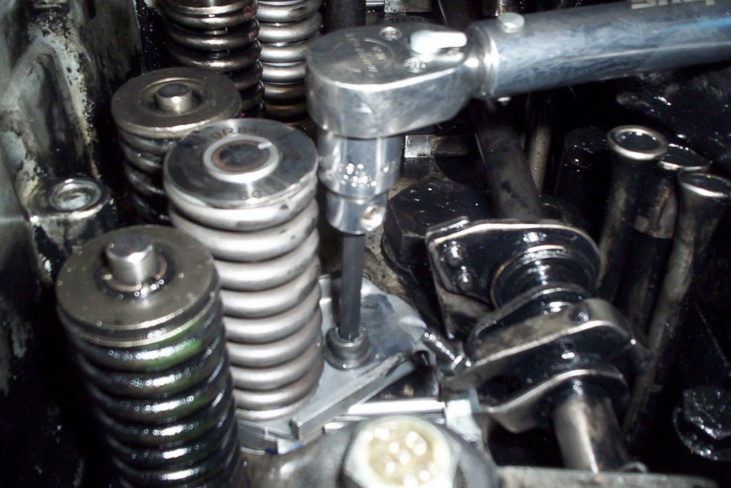
- clean out injector sleeve bore.
- installing o-rings on the injector tip is no longer required since the seating tool creates a seal between the injector body and seat. With the injector main body o-ring installed apply a light film of engine oil.
- seat the injector in the bore of the head and push down firmly on the return spring until a noticeable click is heard.
- turn injector until it engages with fuel control rack.
- torque hold down bolt to 9 ft lbs + or - 2 ft lbs.
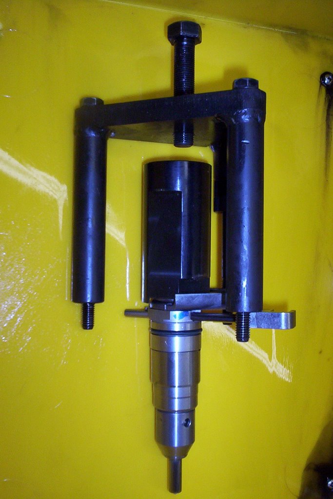
Use injector seating tool to seat injector into it's bore.
- the seating tool is supplied by Caterpillar and must be used or compression may leak past injector into the fuel system.
- re-torque injector hold down bolt when seating procedure is completed.
- picture shows seating tool set up outside of the engine to clearly see how it works. Torque the three seating tool mounting bolts down to 20 ft lbs then seating bolt{top} to 25 ft lbs wait a few seconds then retorque.
The next step is Synchronization which I will post soon. I hope you can use this information when installing an injector on your 3116 Cat Diesel Engine
Subscribe to:
Posts
(
Atom
)