Showing posts with label mechanical repairs. Show all posts

Thursday, August 04, 2011

International Diesel Engine Rebuild Installing Liners

In the past International DT466 Diesel Engines used 2 orings to seal the liner in the block. Here is the upgrade with the one seal. You notice we're using Lubriplate grease to pre-lube the seal. You can also use cooking oil which International recommends, all the Mechanics (myself included) in our shop swear by Lubriplate and it has never failed us.


Installing the liner is the next step.It's recommended to keep the liner seated firmly after installation as pictured here with metric fasteners and washers. The liner protrusion has to be checked as well to maintain a good seal surface for the head gasket. I hope this quick Mechanic information tidbit helped you out.

Saturday, January 29, 2011

Cummins Diesel Engine Fuel Injection Pump Installation

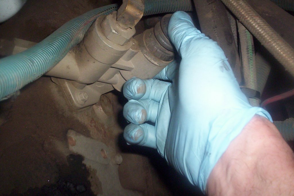
The Cummins Diesel [Engine Model 'C'] fuel injection pump has been repaired, but there are still a few steps to take.


TIMING FUEL INJECTION PUMP:
The fuel injection pump MUST be timed by removing threaded hex cap located on the throttle shaft side of the housing. Remove timing pin from access hole and rotate the pump by hand until the timing tooth inside pump housing lines up with the middle of the access hole.
Engage slotted timing pin as the picture above shows. Install threaded cap hand tight until after injection pump is installed. The injection pump is now in the proper timed position.


PRE-LUBE INJECTION PUMP:
When a repair has been made on these pumps they must be pre-lubed with engine oil. Remove top plug from the governor housing with an Allen wrench. This particular model requires .71 Litres [24 oz.] . Failure to do this could cause damage during start-up.


TIMING THE ENGINE:
The next step is to time the engine by rotating clockwise [viewed from the front] while pushing on timing pin until it engages into the camshaft gear. Engine is now properly timed, the fuel injection pump is ready to INSTALL.


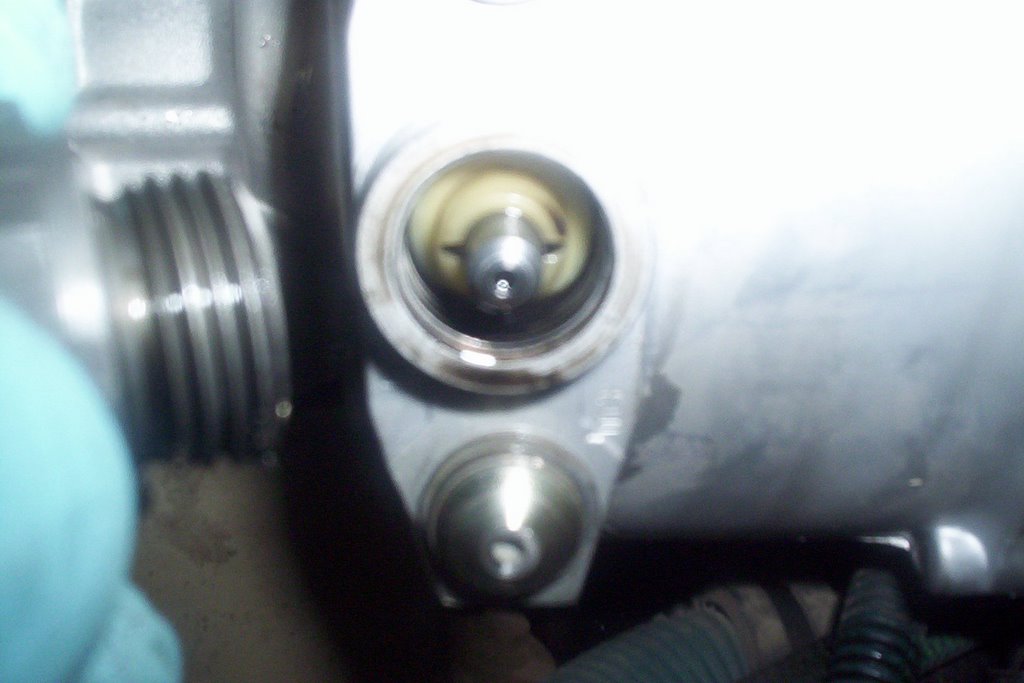
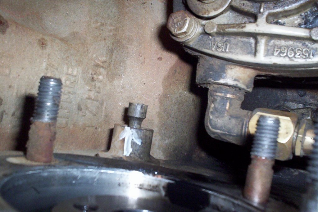
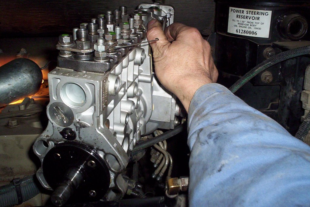
After the 4 mounting bolts are tightened, torque accessory drive gear retaining nut to 106 in. lbs. then DISENGAGE BOTH TIMING PINS. The injection pump timing pin just pulls out, flips around and stays installed on the pump for next time. The engine timing pin just pulls back and stays put.


TORQUE DRIVE GEAR RETAINING NUT:
Now it's time for the final torque 144 ft. lbs. NOTE: torque specs will vary depending on the injection pump model. Now it probably makes sense to you why it's important to disengage both timing pins. They will sheer off very easily being made out of plastic and debris will get into the injection pump housing or engine timing gear housing.


BLEEDING THE FUEL INJECTION SYSTEM:
Once the lines, linkages and accessories have been assembled it's time to bleed the system. Loosen bleeder plug located on the engine side of the injection pump. Operate transfer pump by hand until all air has been bled out of bleeder plug. Tighten bleeder plug.
Crack as many injector lines as you can at each cylinder and crank over engine until there is evidence of fuel at each injector. Stop cranking and tighten injector lines, start cranking engine once again and before you know it you'll have a smokin' diesel engine!

Tuesday, November 30, 2010

Mechanic 12 Volt System Troubleshooting-Reverse Warning System Stuck On

Working on a fleet of buses has some amusing moments. Especially when 12 Volt systems and moisture come into play. Mechanics go to school to get the basics, then you need to use those basics and go much deeper. Experience indeed is the best teacher and mechanic information on symptoms and troubleshooting can be shared and recorded for the benefit of the entire shop and right here on this blog for future use.

Below is what I call a 'Mechanic's Special'

The driver complaint is the back up alarm and reverse lights come on all the time even in neutral. So the first thing to think about is what could possibly cause this to happen without touching the controls. With the key on we have full operation of the back up warning system. The HDX Thomas pusher we are working on has the VIM (vehicle interface module) mounted above the steering axle (Lots of snow and ice). This is the first place to check since the interface module receives the reverse signal from the Trans ECU after the driver selects reverse.   CLICK ON PICTURE TO ENLARGE.
The VIM has relays and fuses (BELOW) to control the circuits on the chassis side of the bus including the high idle, neutral start and reverse warning. Luckily once we pulled off the lid to the VIM we heard a buzzing noise. This is not normal and is a mechanic troubleshooting red flag, you want to look for abnormal mechanical situations.

After opening the VIM up the problem was obvious. The corrosion was making a circuit from battery to the reverse warning system. Moisture, oxygen and 12 Volt electrical circuits love each other and create double trouble after uniting for a given period of time.
Here is my 'KEEP IT SIMPLE' drawing (BELOW) of the circuit in question. The operator chooses reverse, the transmission shifts and the reverse signal is fed to the Vehicle Interface Module to the reverse relay and 12 Volt power feeds the reverse alarm and lights.


Once you know how a circuit works it makes the problem solving much easier and common sense will prevail. This problem can happen anywhere so be prepared. Checking electrical problem circuits and components closest to the environment pays off more times than not. I hope you got something out of this Mechanic Information.

Please leave a comment below and share any 12 volt electrical experiences you've had in the past or just let me know you got something out of this info.

Tuesday, November 23, 2010

Choosing A Mechanic Trade School Over College

Is A Trade School A Better Choice Over College?
Here's an interesting video on people enrolling into a trade school for a 10 month diesel engine training course instead of taking 4 years of college which comes with a much higher tuition. The enrollment fee is a fraction of what college costs and finding a job is faster and easier in the diesel engine mechanic trade.

Once you get your initial training at a trade school the chances of getting a job are much higher. Employers who want to hire a Mechanic for an apprenticeship like to find someone who has the basic training. Having a new kid on the block without any training means more supervision and less production.


Tuesday, October 19, 2010

Stopping Front Brake Rattle With GM® Caliper Kit

Here is a great article from Alldata

By Rich Diegle, Automotive Editor

Owners of several General Motors vehicles may experience a rattling noise coming from the front of their vehicles. The problem affects the following 2000 and 2001 models:

* Buick® Century and Regal
* Chevrolet® Impala, Monte Carlo and Venture
* Oldsmobile® Intrigue and Silhouette
* Pontiac® Grand Prix and Montana

This annoying rattle usually occurs at vehicle speeds under 30 mph (48 km/h) and while driving over bumps. A light application of the brake pedal usually eliminates the noise.

The cause is too much clearance between the front brake caliper bracket and the caliper pins in the bottom of the bracket bores. GM offers a front brake caliper service kit that should eliminate the problem (P/N 18046457). Install the brake caliper kits to both sides of the vehicle using the following service procedure. Each kit contains 2 pins, 2 boots, and 2 packets of grease.

Repair Procedure

(Review safety procedures contained in the ALLDATA® system before beginning)

1. Brake Caliper OneRaise and suitably support the vehicle, then remove both front tires and wheels.

2. Install and hand-tighten at least two wheel nuts to retain the rotor to the hub.

3. Install a large C-clamp (2) over the top of the brake caliper and against the back of the outboard brake pad.

4. Tighten the C-clamp until the caliper piston is pushed into the caliper bore enough to slide the caliper off the rotor, then remove the C-clamp from the caliper.

5. Remove the caliper pin bolts (3) and discard. New bolts are supplied with the service kit.

6. Remove the caliper (1) from the caliper bracket (2) and support the Brake Caliper Twocaliper with heavy mechanic's wire, or equivalent.

7. Using a flat bladed tool or punch, carefully tap the caliper pin boots from the brake caliper bracket and discard.

8. Carefully insert a small screwdriver into the brake caliper bracket bore, then rotate and pull the bushing outward to remove. Discard the bushings.

9. Remove the brake pads from the brake caliper bracket.

10. Thoroughly clean the brake caliper bracket bores of all lubricant.

11. Install the brake pads into the brake caliper bracket.

12. Lubricate the brake caliper bracket bores by dividing the large packet of grease (supplied in the kit) and putting one-half of a packet into each Brake Caliper Threebore.

13. Lubricate the new caliper pin boots by using the small packet of grease (supplied in the kit) only on the bottom internal threads (2).

14. Install the new caliper pin boots into the caliper pin bores (3) on the bracket. Carefully tap boots into bores using a deep well socket or equivalent.

15. Install the caliper over the rotor and onto the caliper bracket. Ensure that the caliper pin boots are not pinched.

NOTE: The leading caliper pin, or top pin, has a bushing as part of the assembly. The trailing caliper pin, or bottom pin, is a solid design.

16. Install the new caliper pin bolts (1) and tighten them to 70 lb ft (95 N.m).
NOTE: It is important to note which caliper pin is designed for the correct bore. The leading caliper pin, or top pin, has a bushing as part of the assembly. The trailing caliper pin, or bottom pin, is a solid design. Ensure that the bolt boots fit securely in the groove of the pin bolts. Be sure not to pinch or tear the boots. If the boots are damaged, they must be replaced.

17. Remove the wheel nuts retaining the rotor to the hub.

18. Repeat the above steps for the other side and install both front tires and wheels.

ALLDATAdiy.com is easy to use and contains all of the original manufacture’s repair, diagnostic and repair procedures. Easy to use navigation and search tools allow you to quickly get to the info you need to do the job. Hyperlinks insure that you can get to related info at the push of a button. Shop Our Products - Click Here