Showing posts with label cummins engine repair. Show all posts
Showing posts with label cummins engine repair. Show all posts
Saturday, June 20, 2015
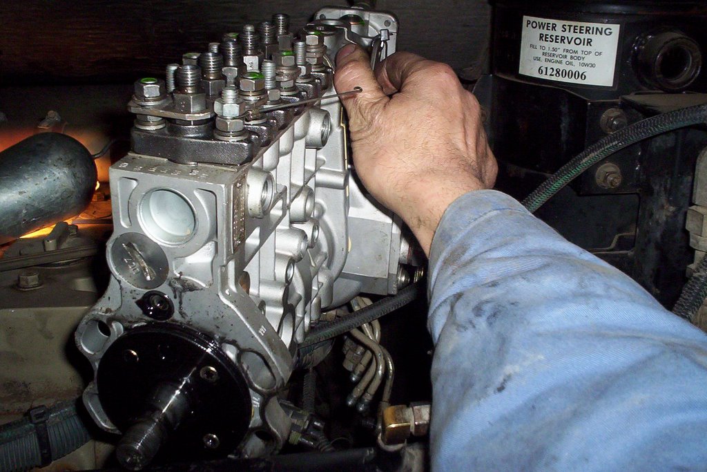
Cummins ISC Diesel Engine CAPS Failure
Cummins CAPS Assembly Repair from John Whelan on Vimeo.
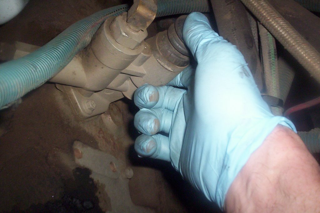
This Cummins ISC diesel engine is in a 1999 Thomas pusher school bus. The engine died suddenly and eventually we found the drive failed in the CAPS pump assembly. Luckily the fuel injection shop we deal with had a core in the back room. We got lucky because the replacement of the pump assembly is around 4,000 dollars.
Most of the ISC diesel engines in our fleet have required a new pump. What happens is multiple engine codes that don't go away. There's a lot going on in the CAPS assy. It develops and controls the high pressure fuel that is distributed at the right time to each injector.
Running at 250 horsepower they are a great engine well suited for a school bus fleet. Other failures were injectors but not very often. The crank and cam sensors act up along with fuel leaks at the electric fuel pump. Our fleet only has 3 of these buses left and they are standing up very well for being thirteen years old.
The fuel pressure sensor in the CAPS accumulator was a regular failure through the years. Cummins did come up with a update on the sensor along with a replacement harness. It only takes 10 minutes to replace the sensor. I personally think Cummins has always been the leader in medium duty diesel engines.
I was an International DT466 fan for years until the emission and electronic version came around. Mechanical fuel injection can not keep up to emission guidelines and the old DT had to be scrapped. They were the best fleet diesel back in it's day but sometimes good things have to come to an end.
At present Cummins has the ISB which runs on DEF (diesel exhaust fluid) and besides the extra maintenance they are the most reliable engines in our fleet. They run seamlessly with the Allison automatic transmissions and the operators really like them for power and we like them for reliability.
Please comment and share this post and thanks for visiting my blog.
Wednesday, September 28, 2011
Cummins N14 Injector Troubleshooting
I found this interesting video from a Mechanic named Daniel who posted an in-depth video on troubleshooting and repairing an injector miss problem on a Cummins N14 injector. This is an electronic diesel model that has solenoid controlled injectors pulsed by the engine ECM. It's an interesting video and very
detailed for the aspiring Cummins N14 Mechanic.
Cummins N14 Injector Troubleshooting and Repair "With this particular injector the way it works is that the solenoid is in an always open position allowing fuel from the rail into the injector and only closes during the downward stroke of the metering plunger so as not to allow the fuel to go back to the rail, rather trapping it in the injector and metering it to the cylinder. Technically, with this particular injector it would be more that the injector fuel supply is “closed” electronically at the injector. danielresume 6 months ago The solenoid is the only aspect of this injector that is electronic and governed by the ECM. It has been my experience that when these solenoids get weak or fail completely the engine might still run at idle without a misfire but under power will miss and have no power. The injector also has a ceramic check ball and metering plunger which will cause the same condition under power if worn as they will allow fuel to escape under pressure rather than injecting to the cylinder." I hope this Mechanic tip has been helpful.
Saturday, January 29, 2011
Cummins Diesel Engine Fuel Injection Pump Installation
 The Cummins Diesel [Engine Model 'C'] fuel injection pump has been repaired, but there are still a few steps to take.
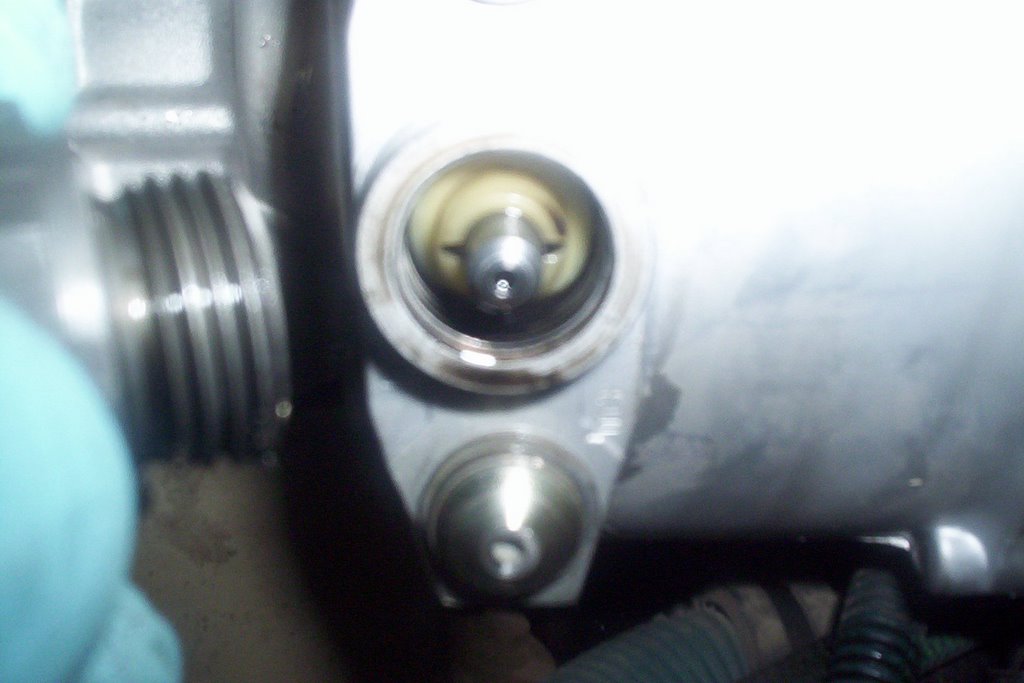
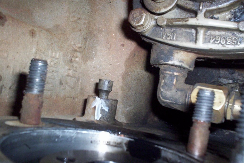
TIMING FUEL INJECTION PUMP:
The fuel injection pump MUST be timed by removing threaded hex cap located on the throttle shaft side of the housing. Remove timing pin from access hole and rotate the pump by hand until the timing tooth inside pump housing lines up with the middle of the access hole.
Engage slotted timing pin as the picture above shows. Install threaded cap hand tight until after injection pump is installed. The injection pump is now in the proper timed position.
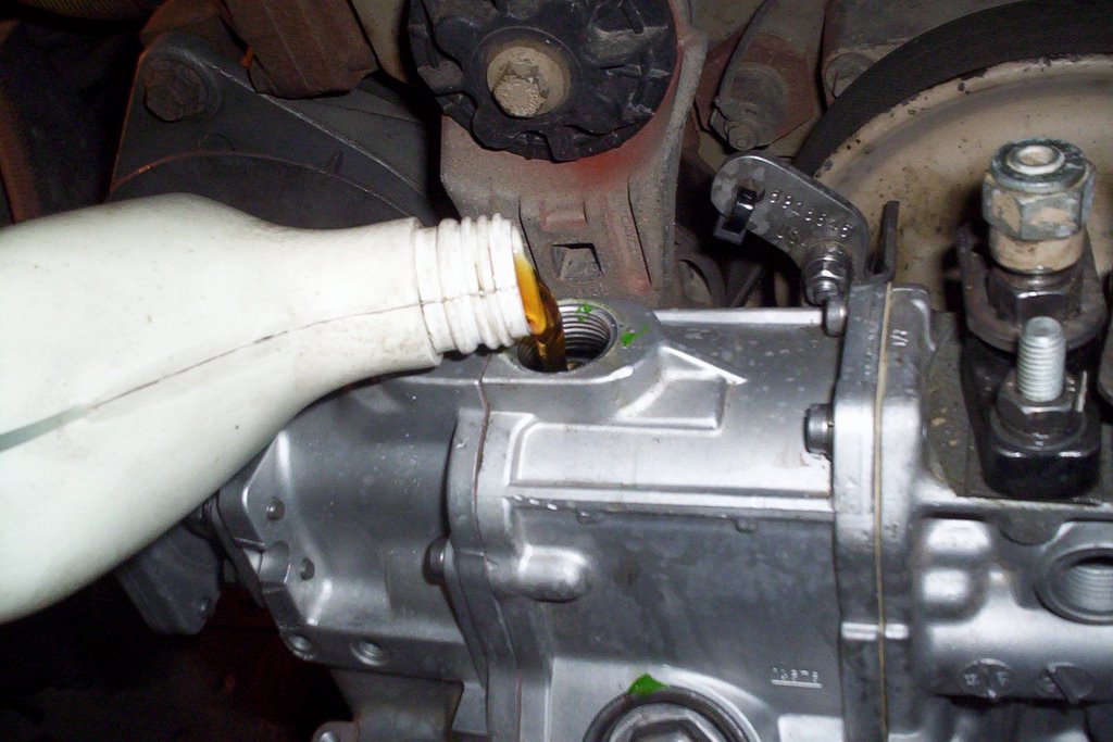
PRE-LUBE INJECTION PUMP:
When a repair has been made on these pumps they must be pre-lubed with engine oil. Remove top plug from the governor housing with an Allen wrench. This particular model requires .71 Litres [24 oz.] . Failure to do this could cause damage during start-up.

TIMING THE ENGINE:
The next step is to time the engine by rotating clockwise [viewed from the front] while pushing on timing pin until it engages into the camshaft gear. Engine is now properly timed, the fuel injection pump is ready to INSTALL.
 After the 4 mounting bolts are tightened, torque accessory drive gear retaining nut to 106 in. lbs. then DISENGAGE BOTH TIMING PINS. The injection pump timing pin just pulls out, flips around and stays installed on the pump for next time. The engine timing pin just pulls back and stays put.
TORQUE DRIVE GEAR RETAINING NUT:
Now it's time for the final torque 144 ft. lbs. NOTE: torque specs will vary depending on the injection pump model. Now it probably makes sense to you why it's important to disengage both timing pins. They will sheer off very easily being made out of plastic and debris will get into the injection pump housing or engine timing gear housing.

BLEEDING THE FUEL INJECTION SYSTEM:
Once the lines, linkages and accessories have been assembled it's time to bleed the system. Loosen bleeder plug located on the engine side of the injection pump. Operate transfer pump by hand until all air has been bled out of bleeder plug. Tighten bleeder plug.
Crack as many injector lines as you can at each cylinder and crank over engine until there is evidence of fuel at each injector. Stop cranking and tighten injector lines, start cranking engine once again and before you know it you'll have a smokin' diesel engine!
Sunday, January 09, 2011
No Start Cummins Diesel Engine
 Cummins Diesel Engine
Here are a few tips and checks you can make when your Cummins Diesel Engine will not start. This information pertains to mechanical injection diesel engines.
Don't feel insulted with some of these checks because the simplest steps have been overlooked many times.
The rule of thumb is Check The Simple Things First!
- When your Diesel engine cranks but will not start - No smoke from exhaust
- Is there fuel in the supply tank? Always check the source on your diesel engine
- Check electric or manual fuel shut-off.
- Is the air intake or exhaust plugged?
- Note: Remember, a diesel engine needs air and fuel to run
- Fuel filter plugged / seperator full of water?-drain as required.
- Your diesel engine injection pump not getting fuel or fuel is aerated. Check fuel flow or bleed fuel system.
- Check inlet restriction to fuel transfer pump
- Inspect lift pump operation. Remove outlet line and crank over engine
- Worn or malfunctioning injection pump
- Internal pump timing incorrect
- Engine camshaft out of time
Check the filters to see if they are still full of fuel, if not you've got a diesel engine that has run out of fuel - a no brainer. I went on a service call once and found out that the operator had filled the tank with gasoline, anything can happen!
Otherwise you have an obvious failure that you have to sink your teeth into. Replace fuel filters if the mileage or hours are excessive.
Check fuel lines from the tank to the primary filter [Fuel/Water Seperator]
Tip: I use a remote fuel container and slip the suction line before or after the primary filter. If diesel engine performance improves you know you have to start checking for faults back to the tank.
This procedure bypasses the fuel tank and lines up to that point which tells you if the problem exists in those areas i.e. restriction or split/cracked fuel line or bad pick-up tube in the tank.
Pull output line off of the lift pump on the side of the block and crank engine over and check for fuel output.
Prime fuel system with primer pump and bleed the injection pump, once primed crack injection lines at the injection pump and observe for fuel output.
In most cases you will find a problem up to this point, if not check injection pump timing or check to see if the camshaft gear is actually driving the injection pump. These failures are not common at all.
I hope these tips help you troubleshoot your Cummins Diesel Engine.
Monday, November 22, 2010
Cummins ISB Troubleshooting Coolant In The Lubricating Oil

However no diesel is perfect so follow me through this quick troubleshooting procedure if you experience coolant in the lubricating oil.
1. The first thing to check is the lubricating oil cooler. The engine oil is cooled by way of the coolant running through a sealed core inside the housing. If it develops a leak you're stuck with coolant getting in the oil. The coolant core can be tested and replaced.
2. The next possibility is the air compressor cylinder head is cracked, has a defective casting (porous) or the head gasket is defective. This is an overlooked cause, the cooling system from the engine is connected to the compressor running through the compressor cyl. head.
3. If your cummins
4. The engine cylinder head is the next possibility with a leaking core or defective expansion plugs. The head must be checked out with a pressure test and magniflux test to find any leaks or cracks.
5. Last but not least is the worst case scenario, the cylinder block. If it's cracked or porous you may be looking for a replacement block or reman (remanufactured) engine.
These are mechanic tips that you can use to get you started finding the cause of coolant in your engine oil.
CHECK OUT ALL MY PREVIOUS POSTS ON THE CUMMINS ISB ENGINE
Friday, June 04, 2010
Cummins ISC Diesel Engine Fuel In Oil Repair.

The Cummins ISC Diesel Engine is a great performer, we have several in our fleet and they are a very durable diesel engine. As with any engine there are failures and in this case we experienced the oil level increasing to an over full condition. One test that told us it was fuel in the oil was the oil sample analysis. We took a sample and the guys at BTA in Kamloops faxed over a report to let us know it was in fact diesel fuel.
Another tell tale red flag was the oil pressure was dropping below normal along with a splatter of oil on the rear engine compartment door. The viscosity decreased making the oil thinner causing these conditions. We actually went through this repair before and the symptoms were exactly the same (that's what happens when you have a fleet with the same drive train).
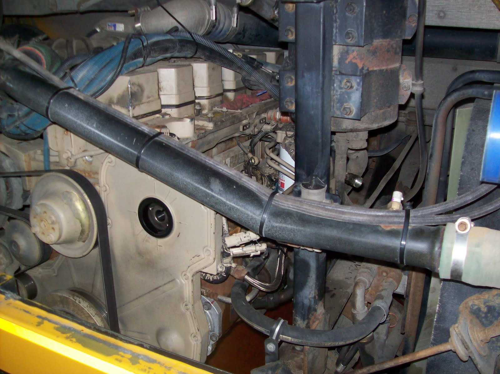
The CAPS Fuel Pump has to be replaced to repair this condition since it provides the high pressure fuel and injection delivery. It runs directly off the accessory gear and is about the same size as a 2 cylinder air compressor. The fuel lines and accessories have to be removed along with the pump accessory drive gear. The first thing to do after this repair is change the engine oil and get rid of that thinned out engine oil.
Monday, April 06, 2009
Cummins Diesel Repair - ISC Model
 This particular Cummins diesel repair was necessary because of an indirect code that was finally traced to the camshaft endplay. There are 2 sensors installed to the backside of the timing cover just below the top drive gear (the 2 black round shaped sensors are visible to the right of the cam shaft bearing bore). One is the camshaft position sensor the other is the engine speed sensor.
 To remove the camshaft the rocker arms and shafts must be removed first. The wooden dowels act as holding devices that jam into the solid lifters that ride on top of the cam lobes. Once the dowels are installed elastic bands are used to hold them secure while removing the camshaft. This saves a lot of time not having to pull the cylinder head.
 The camshaft endplay was excessive which caused the sensor problem/codes to become a regular occurrence. The first step we took was to change the sensors, this cured the problem for several weeks but the fault always came back to haunt us. The camshaft showed signs of wear on the shoulder where the gear sits and the cam lobes as well. There is a thrust washer that goes between the gear and the engine block to help with endplay movement.
 If you have to do this job in a Thomas ER Pusher Bus you will have to remove the rear engine mounts and lower the engine enough to get the rear pushrods out of the engine. The solid floorboards above are not designed to allow the pushrods enough headroom for removal.
The cam gear has to be heated to 400 degrees Fahrenheit to install back onto the camshaft. We elected to replace the gear as well as the camshaft. If you are a Diesel Mechanic this is a Cummins Engine repair you may have to go through one day. I hope this mechanic info has helped you understand the procedures involved in this operation.
Wednesday, March 25, 2009
Cummins Diesel Engine Drive Gears
 If you were to remove the front cover off of any diesel engine you will come across a series of drive gears. No belts or chains here, you're looking at the timing gears that make this diesel engine run. Each gear is timed to each other with specially placed marks that must be lined up during assembly.
Enlarge this picture by clicking on it and you should see the timing marks on the crank and cam gears. They look like center punch marks one on the crank and two marks on the camshaft.
The crankshaft and camshaft gears are driven together to provide proper valve and piston timing for combustion to occur. Fuel injection timing on the Cummins C Model diesel engine (pictured here) is accomplished by inserting a pin into the injection pump drive gear (top right).
The pump in turn has a pin in the side of it's housing that has to be removed, flipped around & aligned into the injection pump shaft setting it for injection on #1 cylinder.
The oil pump is also driven off of the crank gear and idler gear. The air compressor is located lower right without it's drive gear installed.
Wednesday, December 24, 2008
Cummins Engine Repair - Camshaft Gear Noise
 Here's an email I received from Jonah Barnes, Lead Mechanic for the School District in Sierra Vista, Arizona. He noticed a noise coming from the front end of a Cummins C Diesel Engine. It turned out to be the camshaft gear. The photos tell the story and I'm amazed how long this gear lasted. It just goes to show how durable a quality metal casting can be and how long it can take a pounding without blowing apart. This gear would have made a huge mess if it exploded inside the timing cover.
"Quote"
Hello John,
It really wasn't too noisy actually. When the compressor placed an added load on the cam gear it would actually rock the gear back and forth and "knock" against the front cover. It almost really did sound like a " bongo drum".
According to the other mechanics who have worked here longer than I the previous attempts of replacing the compressor would cause it to be quiet for about a week or so then it would go back to the intermittent drum beat. They were adament that it was the compressor again and they were just getting bad ones.
They even went as far as replacing the fan hub and alternator a few times with no luck. I used redneck diagnosis and used a piece of fuel line and placed one end in my ear and the other end I listened around until I was sure it was in the front timing cover.
It actually made the sound faintly using the hose when the compressor governor unloaded but it was not as pronounced as when the compressor was running. I have only been with the school district here just a few months but have been a mechanic most of my life.
I have run into a lot of different broken things but this gear being broken like this and the engine still running down the road and running routes without missing a beat (literally) is pretty amazing I think.
They said it has been doing this almost 3 years but no one really thought it was that serious. I contacted cummins here and they know of no recalls on the gear but they are available from cummins for about $350.00 US.
I am originally from Indiana and my dad was an engineer for cummins for several years and he was pretty amazed too that it was still running. I don't think it would have much longer though. I will be sure to keep you informed of other mysterious problems I encounter on my end.
The more information out there the more it can help other people who are sitting there scratching there head. We tend to get a lot of life out of a bus out here because of not having to deal with rust issues so there are several high mileage buses just waiting to keep me employed!
Thanks again for your help.
Jonah Barnes
Lead Mechanic
Sierra Vista, Arizona
"Unquote"
Thanks to Jonah for sharing!
I love to receive emails with Mechanic Information sharing experiences of real life repairs & troubleshooting. This is helpful for Mechanics & Truck Owners who always have new and interesting problems to solve.
Saturday, April 26, 2008
Avoiding Cummins Engine Repairs With Regular Tune-ups.
 We recently had a Cummins Diesel Engine with a power complaint. One adjustment that gets overlooked is valve adjustment. This particular engine gained substantial power after adjusting the valves which required an average of 1/4 of a turn to meet specs. So this simple tune-up procedure should never be overlooked and must be carried out on regular basis.
The following is a valve adjustment on a Cummins ISB Diesel Engine: Valve adjustment on a Cummins Engine Repair is the final step. Engine position is very important because the intake and exhaust valves must be in the closed position.
Rotate the engine clockwise [looking from the front] until #6 cylinder rocker arms are both rocking. When you're on the correct stroke the exhaust valve will be moving into the closed position, then once it closes keep rotating the engine until the intake valve JUST starts to open. You are now on #1 Compression Stroke & ready to adjust 1/2 of the engine valves.Note: The crossheads pictured here on top of the valve stems [#5 & #6 Cyl] are located with the elongated contact surface towards the exhaust manifold. The Rocker arms are held down on aluminum cradles with one retaining bolt and torqued to 27 ft. lbs.
 Cummins 24 Valve Turbo Diesel Valve Adjustment Specs.
With the Engine on #1 Compression Stroke.
*Adjust #1 #2 #4 Intake Valves to .010 inch.
*Adjust #1 #3 #5 Exhaust Valves to .020 inch.
*Rotate Engine One Full Turn. #1 Cylinder Valves will rock like #6 did previously positioning the engine on #6 Compression Stroke.
*Adjust #3 #5 #6 Intake Valves.
*Adjust #2 #4 #6 Exhaust Valves.
I hope this mechanic information has helped you: It's not hard to adjust valves on a Cummins 24 Valve Turbo Diesel once you get the hang of it. All you have to know is how to position the engine correctly, the valve settings and some basic tools. That's it for now on Cummins Engine Repair.
Recommended: Diesel Engine Repair Manuals

Saturday, February 09, 2008
Cummins Engine Repair- ISC Engine Code 434
 Cummins Engine Repair not only involves mechanical but electronic repairs as well. The ISC model has an ECM that sends and receives messages that controls every performance aspect of this engine. The main source of power is the battery that depends on wiring that feeds the Cummins ECM sufficient voltage to run the engine systems.
Pictured is the laptop shot of an active code #434 a power interruption that derated the engine to a crawl. Derating protects the engine from sustaining high speeds and rpms which would cause more severe damage. This ISC Cummins Engine is in a 1999 Thomas School Bus Saf-T-Liner. With an active code you can retrieve it with the diagnostics switch [on the dash] & ignition switch turned on. The code will beep each number with a pause, in this case 4 beeps 3 beeps 4 beeps with a pause in between each #.

A closer look [click on photo to enlarge] shows numerous fuses on the positive feed wire to the Engine ECM [electronic control module]. Our code information is telling me there is a power problem so "the first thing to check is the Source."

Using a digital ohmmeter check the fuses for continuity and clean all the connections.
Note: Before this maintenance step I could not get a reading on my laptop, there was a communication error between the engine and the "Cummins Insite" software.
After cleaning all the connections and testing the batteries the communication problem was erased and the code disappeared.

There is a variety of 7.5 and 10 amp fuses inline with battery to ECU supply power. I traced the wiring back along the frame as well to check out any other possible problems. The rule of thumb in this situation is to check connections and wiring closest to the environment and work your way up the line.
 Using a Snap-On Micro Vat Battery Tester I concluded that all the batteries were in good condition. This tester does a very quick assessment of battery condition and also tests starting and charging systems quickly.
The Conclusion to this problem was simple, servicing the battery connections which had enough resistance to cause the #434 code to occur. It makes sense since the ECM reads Voltage at a very sensitive level.
After an extensive road test the code did not come back and this experience was a good one telling me [and you the reader] to always check the simple things first!
Now we're ready for the next challenge with Cummins Engine Repair.
Recommended: Diesel Engine Repair Manuals
Saturday, January 26, 2008
Cummins Engine Repair-Adjusting Valves ISB
 Valve adjustment on a Cummins Engine Repair is the final step. Engine position is very important because the intake and exhaust valves must be in the closed position.
Note: The crossheads pictured here on top of the valve stems [#5 & #6 Cyl] are located with the elongated contact surface towards the exhaust manifold. The Rocker arms are held down on aluminum cradles with one retaining bolt and torqued to 27 ft. lbs.
Cummins 24 Valve Turbo Diesel Valve Adjustment Specs.With the Engine on #1 Compression Stroke.
*Adjust #1 #2 #4 Intake Valves to .010 inch.
*Adjust #1 #3 #5 Exhaust Valves to .020 inch.
*Rotate Engine One Full Turn. #1 Cylinder Valves will rock like #6 did previously positioning the engine on #6 Compression Stroke.
*Adjust #3 #5 #6 Intake Valves.
*Adjust #2 #4 #6 Exhaust Valves.
It's not hard to adjust valves on a Cummins 24 Valve Turbo Diesel once you get the hang of it. All you have to know is how to position the engine correctly, the valve settings and some basic tools. That's it for now on Cummins Engine Repair.
Recommended: Diesel Engine Repair Manuals
Sunday, January 20, 2008
Cummins Engine Repair - Installing Injectors
 Cummins Engine Repair
 Replace o-ring on the injector body and copper sealing washer on injector tip. Position into head with orifice pointing towards fuel connector tube opening. [click photo to enlarge]
 The injector hold down installs only one way to index the injector position aligning it with the fuel connector tube. The hold down retaining bolts are torqued to 89 in. lbs.
 Install fuel connector tubes [with new o-ring] into the head bore. The tube has a tapered tip that aligns with injector body. Torquing the fuel line retaining nut forces contact and a proper seal between the injector body and connector tube.
 The injector lines are what retains contact between the fuel injector and connector tube. Torque the fuel line nuts to 28 ft. lbs. using a crowfoot wrench.
That's it for this post with more to come on Cummins Engine Repair.
Recommended: Diesel Engine Repair Manuals
Saturday, January 19, 2008
Cummins Engine Repair - Torquing Cylinder Head Bolts
Cummins Engine Repair - Torquing Head Bolts on a Cummins 24 valve turbo diesel. The torque pattern is circular starting from the middle and working both ways to each end of the cylinder head.
Torque Specs Are As Follows:
Recommended: Diesel Engine Repair Manuals

Torque Specs Are As Follows:
- 59 ft. lbs.
- 77 ft. lbs.
- Check again at 77 ft. lbs.
- Finally advance each head bolt an additional 90 degrees
- Since each flat side of the "hexagonal" bolt head is 60 degrees [60 X 6 sides=360 degrees]
- One flat and 1/2 = 90 degrees.
This is the most important step when replacing any engine cylinder head gasket. If the proper torque specs are not followed bolt stretch [over torqued] or coolant leaks [under torqued] will occur and you'll have to start all over again with your Cummins Engine Repair.
Recommended: Diesel Engine Repair Manuals
Sunday, January 13, 2008
Cummins Engine Repair - ISB Model
 Cummins Engine Repair on a 2002 Thomas Freightliner School Bus. The head gasket was leaking coolant from the right front corner. The first step is to unhook the battery and drain the coolant.
The Turbocharger [pictured] can be removed as a complete assembly attached to the exhaust manifold. The fuel lines are removed from the opposite side.
 The Cummins 24 valve turbo diesel has 2 intake valves and 2 exhaust valves for each cylinder. The parts displayed here have been cleaned and inspected for pitting, hard surface wear and corrosion [head bolts]. Head bolts are measured for length, with a special guage provided by Cummins [usually comes with the head gasket kit].
 The cylinder head itself weighs approxiamately 80 lbs. [3 Mechanics removed the head off the block manually and it's a clumsy operation!]
Here I'm using the hydraulic hoist to install the head, the only problem we encountered was the reach was not long enough on the hoist boom so I removed the front wheel to enable rolling the hoist into the engine compartment further. [An overhead hoist would be perfect for this job!]
 Cummins Engine Repair involves cleaning and inspecting, especially when it comes to the block surface. Look for any cylinder scoring and cracks then run a straight edge on the block surface where only a few thousands of an inch wear is allowed. Use a .003 in. feeler guage to check the block wear.
 Removing the injectors is easy once the fuel connector tubes inside the head are removed [Below]. The injectors have hold downs on top that have 2 fasteners, when removed the injector has a threaded hole on top that can be used to pull the injector out which is held in by an o-ring.
NOTE: Remove injectors before removing cylinder head, the injector tips protrude past the head surface.
 The fuel connectors in the Cummins 24 valve turbo diesel have an o-ring seal and connect the fuel between the fuel injector lines and the injectors. They are tapered and have a machine fit into the injector body. The injector hold downs only install one way and index the injector in the head bore so the connector tube aligns with the injector.
I hope this basic overview has helped you get more aquainted with Cummins Engine Repair
More To Come!
Recommended: Diesel Engine Repair Manuals
Subscribe to:
Posts
(
Atom
)